Do not remove the pressure cap from a hot engine. Wait until the coolant temperature is below 50°C [120°F] before removing the pressure cap. Heated coolant spray or steam can cause personal injury.
WARNING
Coolant is toxic. Keep away from children and pets. If not reused, dispose of in accordance with local environmental regulations.
Before removing gears, read Engine Base Timing. Refer to Procedure 001-088.
Remove the water pump drive belt. Refer to Procedure 008-003.
Remove the alternator drive belt. Refer to Procedure 013-005.
Remove the fan hub assembly. Refer to Procedure 008-036.
Remove the crankcase breather tube. Refer to Procedure 003-018.
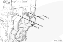
Remove the alternator. Refer to Procedure 013-001.
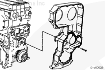
Immediately upon removal of the front gear housing a plug must be inserted into the cylinder block oil passage drilling. Failure to insert the oil passage plug can result in a bearing failure, crankshaft failure, or both.
The reusable plug, Part Number 4918320, is included in protective plug kit, Part Number 4918319. This plug is necessary to prevent debris from entering the lubrication system during the repair.
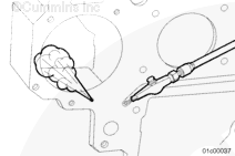
Insert the plug into the front oil passage.
Firmly push the plug into the oil passage to prevent all debris from entering the lubrication system when cleaning the gasket surface.
When using solvents, acids, or alkaline materials for cleaning, follow the manufacturer’s recommendations for use. Wear goggles and protective clothing to reduce the possibility of personal injury.
WARNING
When using a steam cleaner, wear protective clothing and safety glasses, or a face shield. Hot steam can cause serious personal injury.
WARNING
Wear appropriate eye and face protection when using compressed air. Flying debris and dirt can cause personal injury.
CAUTION
If the oil passages are not plugged before cleaning, a crankshaft failure can occur.
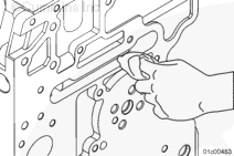
Clean gasket surfaces by hand with a gasket scraper or cleaning pad, Part Number 3823258. If the gasket material residue can not be felt with a finger, the surface is ready to accept the new gasket.
Use steam or solvent to clean the gear housing and dry with compressed air.
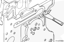
Remove the protective plug from the cylinder block oil passage. Make sure no debris enters the lubrication system. Use a clean shop towel, carefully wipe out the oil passage and inspect to make sure no debris is left in the passages.
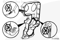
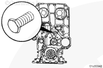
The gear housing has the words “Special Capscrew” cast into the housing at the number 1 mounting location (see illustration). This capscrew must be the short head capscrew to prevent contact between the capscrew and the idler gear.
Do not remove the pressure cap from a hot engine. Wait until the coolant temperature is below 50°C [120°F] before removing the pressure cap. Heated coolant spray or steam can cause personal injury.
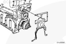
Install the accessory bracket. Refer to Procedure 001-082.
Install the retaining brace bracket. Refer to Procedure 001-081.
Install the crankshaft position sensor. Refer to Procedure 019-042 in the Signature, ISX, and QSX15 Service Manual, Bulletin 4021334. Install the capscrews at the front of the oil pan.
Install the lower idler scissor gear. Refer to Procedure 001-088.
Install the air compressor. Refer to Procedure 012-014.
Install the adjustable idler gear. Refer to Procedure 001-088.
Install the valve and injector camshaft scissor gear. Refer to Procedure 001-088.
Install the water pump. Refer to Procedure 008-062.
Install the upper and lower gear covers. Refer to Procedures 001-079 and 001-080.
Install the crankcase breather tube. Refer to Procedure 003-001.
Hello, I'm Jack, a diesel engine fan and a blogger. I write about how to fix and improve diesel engines, from cars to trucks to generators. I also review the newest models and innovations in the diesel market. If you are interested in learning more about diesel engines, check out my blog and leave your feedback.
View all posts by Jack
 WARNING


 CAUTION
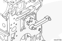


;)
;)
;)
;)
;)
;)
;)
;)
;)
;)
;)
;)
;)
;)
;)
;)
;)
;)
;)
;)
;)
;)