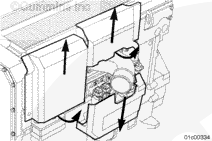
NOTE: Each nylon cover is attached to the engine by a combination of push on and slide in tabs. The top two covers are removed by first pulling (at the location marked “Pull Here”) the bottom of the covers away from the engine until the tabs are released, then sliding the covers upward to remove them from the accessory bracket. The lower cover is removed by pulling (at the location marked “Pull Here”) the top of the cover away from the engine until the tabs are released, then sliding downward.
NOTE: Each nylon cover is attached to the engine by a combination of push on and slide in tabs. The top two covers are removed by first pulling (at the location marked “Pull Here”) the bottom of the covers away from the engine until the tabs are released, then sliding the covers upward to remove them from the accessory bracket. The lower cover is removed by pulling (at the location marked “Pull Here”) the top of the cover away from the engine until the tabs are released, then sliding downward.
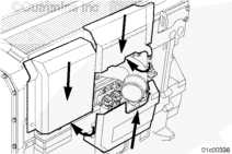
NOTE: The top two covers are installed by sliding the cover down into the slots on the accessory bracket, then pushing the bottom of the cover toward the engine onto the cover mounting tabs. Install the bottom cover by sliding the cover upward into the slots on the accessory bracket, mounted on the IFSM, then pushing the top of the cover toward the engine onto the cover mounting tabs.
NOTE: The top two covers are installed by sliding the cover down into the slots on the accessory bracket, then pushing the bottom of the cover toward the engine onto the cover mounting tabs. Install the bottom cover by sliding the cover upward into the slots on the accessory bracket, mounted on the IFSM, then pushing the top of the cover toward the engine onto the cover mounting tabs.
Install the three composite nylon covers.
NOTE: This step does not apply to Power Generation applications.
Hello, I'm Jack, a diesel engine fan and a blogger. I write about how to fix and improve diesel engines, from cars to trucks to generators. I also review the newest models and innovations in the diesel market. If you are interested in learning more about diesel engines, check out my blog and leave your feedback.
View all posts by Jack


;)
;)
;)
;)
;)
;)
;)
;)
;)
;)
;)
;)
;)
;)
;)
;)
;)
;)
;)
;)
;)
;)