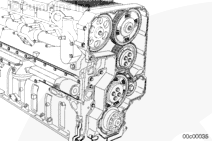
Two front gear train combinations are currently utilized on the Signature™, ISX, and QSX15 engines. Signature™, ISX3, ISX2, and QSX15 engines use a scissor gear for the lower idler gear and the injector cam gear. ISX1 does not use a scissor gear at the idler location.
ISX2 engines built between January, 1999 and January, 2000 utilized a scissor gear for the lower idler gear only. The injector cam gear was a straight cut spur gear, similar to the ISX1. After January, 2000, the ISX2 has scissor gears for both the cam and lower idler.
This procedure describes the removal, inspection, and installation of the different gear combinations.
Do not attempt to remove any gears before reading scissor gear definitions. Serious personal injury or engine damage can result if instructions are not followed.
The following terms describe the conditions of the scissor gears for removal, installation, and operation.
The gear teeth are loaded (functional) and are spread between the mating gear teeth.
The gear is loaded by tightening all of the adjusting screws. The gear teeth will be spread and no movement will be felt against the valve cam gear. The gear will be in the loaded condition for engine operation.
QSX15 engines are equipped with dual vibration dampers. The crank pin mark is located on the damper closest to the engine.
Rotate the crankshaft clockwise until the ”insert pin” mark on the outside diameter of engine vibration damper is aligned with the mark on the gear housing.
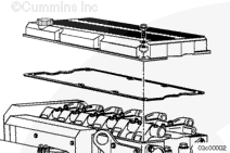
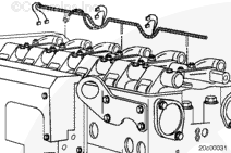
Removing the rocker lever shafts removes the load from the camshafts. This allows the camshafts to be rotated when installing the timing wedges and the camshaft gears are not installed.
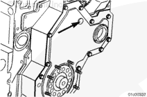
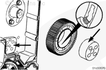
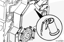
Removal of the lower front cover is not required when setting the gear backlash on engines that utilize all non-scissor gears. An access hole is provided to insert a shim between the lower non-scissor idler gear and the adjustable idler gear. The access hole is sealed with a plug.
It will be helpful to push the gear cover plug out from the rear. It is not necessary to remove the lower gear cover to push out the plug.
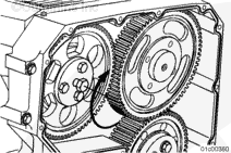
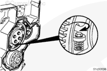
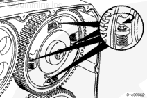
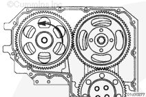
The injector camshaft scissor gear must be unloaded during removal of the valve camshaft gear. To unload the gear, two of the gear screws must be backed out far enough to allow the teeth on the scissor gear to be aligned.
Unload the injector camshaft scissor gear.
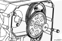
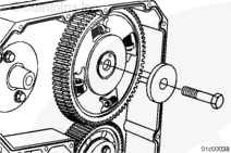
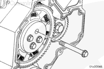
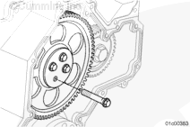
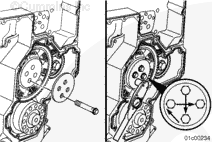
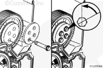
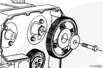
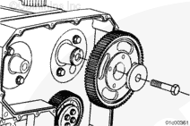
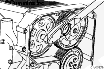
Remove the valve camshaft gear mounting capscrew and washer.
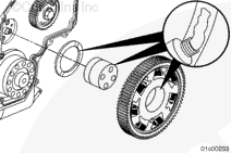
Early production engines were not equipped with puller holes in the valve camshaft gear. A 3-jaw gear puller must be used for gears that do not have puller holes. The injector and valve gear puller, Part Number 3163069, can be used for gears that have puller holes.
Install the gear puller, Part Number 3163069.
Install the valve camshaft gear mounting capscrew completely.
Loosen the capscrew two turns.
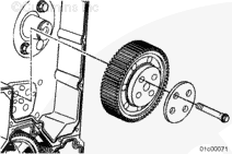
Use the gear puller to remove the valve camshaft gear from the camshaft nose.
Do not completely remove the camshaft gear mounting capscrew when the 3-jaw puller is used. The capscrew serves as a safety catch by preventing the gear from shooting off of the camshaft nose.
Remove the valve camshaft gear mounting capscrew, spacer, and valve camshaft gear.
When using solvents, acids, or alkaline materials for cleaning, follow the manufacturer’s recommendations for use. Wear goggles and protective clothing to reduce the possibility of personal injury.
WARNING
Some solvents are flammable and toxic. Read the manufacturer’s instructions before using.
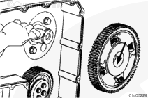
Use a lint free cloth and solvent to clean the Loctite™ residue from the nose of the camshaft.
Remove the rear injector camshaft cover plate before removal of the injector camshaft gear or camshaft. The force required to remove the camshaft gear creates sufficient backwards movement of the camshaft to crack the rear cover plate.
When using solvents, acids, or alkaline materials for cleaning, follow the manufacturer’s recommendations for use. Wear goggles and protective clothing to reduce the possibility of personal injury.
WARNING
Some solvents are flammable and toxic. Read the manufacturer’s instructions before using.
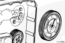
Use a lint free cloth and solvent to clean the Loctite™ residue from the nose of the camshaft.
Remove the rear injector camshaft cover plate before removal of the injector camshaft gear or camshaft. The force required to remove the camshaft gear creates sufficient backwards movement of the camshaft to crack the rear cover plate.
When using solvents, acids, or alkaline materials for cleaning, follow the manufacturer’s recommendations for use. Wear goggles and protective clothing to reduce the possibility of personal injury.
WARNING
Some solvents are flammable and toxic. Read the manufacturer’s instructions before using.
Use a lint free cloth and solvent to clean the Loctite™ residue from the nose of the camshaft.
The lower idler scissor gear must be unloaded during removal. To unload the gear, two of the gear screws must be backed out far enough to allow the teeth on the scissor gear to be aligned.
The lower scissor idler gear must be unloaded during installation. To unload the gear, two of the gear screws must be backed out far enough to allow the teeth on the scissor gear to be aligned.
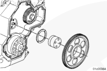
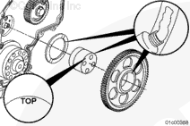
Apply Lubriplate™ to the thrust bearing, shaft, and lower scissor idler gear.
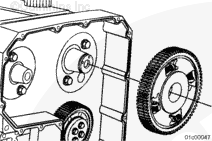
Install the thrust bearing, shaft, and lower scissor idler gear. The shaft must be installed with the word “TOP” (stamped on the end of the shaft) toward the top of the engine.
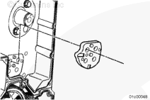
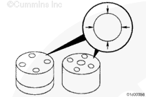
The lower idler scissor gear front retainer plate is larger in diameter than the adjustable idler retainer plate. The slots in the plate go toward the scissor gear
Install the retainer and capscrews.
Tighten all capscrews in a star pattern.
Torque Value:
30 n.m
[22 ft-lb]
Rotate each capscrew an additional 60 degrees in the same sequence as above.
Make sure all the scissor gear screws are tightened to the proper torque so that they do not back out during engine operation. Severe engine damage can occur.
Load the lower idler scissor gear by tightening all of the gear screws.
Apply Lubriplate™ to the thrust bearing, shaft, and lower non-scissor idler gear.
Install the thrust bearing, shaft, and lower non-scissor idler gear. The shaft must be installed with the word “TOP” (stamped on the end of the shaft) toward the top of the engine.
The lower idler non-scissor gear front retainer plate is larger in diameter than the adjustable idler retainer plate. The slots in the plate go toward the scissor gear
Install the retainer and capscrews.
Tighten all capscrews in a star pattern.
Torque Value:
30 n.m
[22 ft-lb]
Rotate each capscrew an additional 60 degrees in the same sequence as above.
Apply Lubriplate™ to the spacer, shaft, and adjustable idler gear.
It is possible to install the shaft in an incorrect orientation; however, it will not be possible to set the gear backlash correctly.
Install the spacer, shaft and adjustable idler gear. The shaft must be installed with the word “TOP” (stamped on the front face of the shaft) oriented toward the top of the engine.
The adjustable idler front retainer plate is smaller in diameter than the lower idler scissor gear retainer plate. The slots on the retainer plate go toward the gear.
The adjustable idler gear is installed loosely, because it is moved into its final position later in the timing process.
Install the retainer and capscrews. Finger-tighten the capscrews and then loosen by one “flat,” which is 60 degrees.
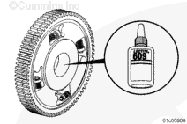
The injector camshaft nose and injector camshaft scissor gear must be clean and dry prior to assembly. Wipe off the taper surface with a clean lint-free cloth and apply a thin coat of Loctite™ 609, Part Number 3823718, to the inside diameter of the camshaft gear. Use care not to contaminate the joint with oil prior to assembly or engine damage may occur.
The injector camshaft scissor gear must be unloaded during installation. To unload the gear, two of the gear screws must be backed out far enough to allow the teeth on the scissor gear to be aligned.
The injector camshaft nose and injector camshaft non-scissor gear must be clean and dry prior to assembly. Wipe off the taper surface with clean a lint-free cloth and apply a thin coat of Loctite™ 609, Part Number 3823718, to the inside diameter of the camshaft gear. Use care not to contaminate the joint with oil prior to assembly or engine damage may occur.
The valve camshaft nose and valve camshaft gear must be clean and dry prior to assembly. Wipe off the taper surface with a clean lint-free cloth and apply a thin coat of Loctite™ 609, Part Number 3823718, to the inside diameter of the camshaft gear. Use care not to contaminate the joint with oil prior to assembly or engine damage may occur.
Do not set backlash between the adjustable idler gear and the lower scissor idler gear. Severe engine damage can occur.
This backlash step works with the scissor type injector camshaft gear and lower idler gear, and the non-scissor injector camshaft gear with a scissor type lower idler gear.
The injector camshaft scissor gear must still be unloaded during this step. To unload the gear, two of the gear screws must be backed out far enough to allow the teeth on the scissor gear to be aligned.
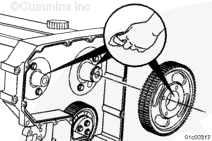
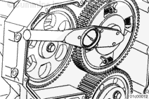
Insert, as shown, a narrow shim (0.25 mm [0.010 in]) into the gear teeth mesh between the adjustable idler gear and the wide (rear side) gear of the injector camshaft scissor gear.
NOTE: The gear backlash set procedure for engines that have a non-scissor injector camshaft gear and a scissor type lower idler gear is the same as that of engines that utilize two scissor type gears.
Use hand pressure, only, to move the adjustable idler gear toward the center of the engine (into mesh), so there is no gap on either side of the shim.
Both of the camshaft gears will rotate slightly on the camshafts during this step.
Slight drag will be felt on the shim while pulling the shim in and out.
Removal of the lower front cover is not required when setting the gear backlash on engines that utilize all non-scissor gears. An access hole is provided to insert a shim between the lower non-scissor idler gear and the adjustable idler gear. The access hole is sealed with a plug. The plug can be pushed out from the rear side without removing the gear cover.
The following procedure will be shown with the lower gear cover removed.
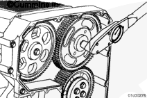
Insert, as shown, a shim (0.25 mm [0.010 in]) into the gear teeth mesh between the adjustable idler gear and the injector camshaft gear. The shim is inserted on the load side of the gear teeth.
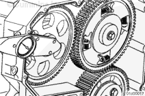
Insert, as shown, a shim (0.25 mm [0.010 in]) into the gear teeth mesh between the adjustable idler and the lower non-scissor idler gear. The shim is inserted on the load side of the gear teeth.
Use hand pressure, only, to move the adjustable idler gear so there is no gap between the teeth and either side of the shims.
Both of the camshaft gears will rotate slightly on the camshafts during this step.
Slight drag will be felt on the shim while pulling the shim in and out.
Make sure all the scissor gear screws are tightened to the proper torque so that they do not back out during engine operation. Severe engine damage can occur.
Load the injector camshaft scissor gear by tightening all of the gear screws.
Torque Value: 28 n.m [248 in-lb]
The valve camshaft gear will rotate slightly on the valve camshaft during this step.
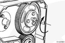
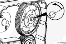
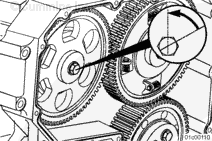
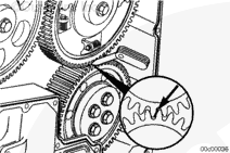
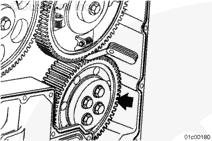
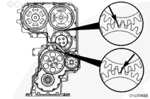
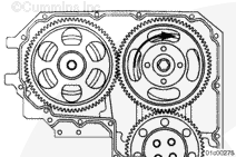
Use hand pressure only to rotate the injector camshaft gear clockwise until the gear train backlash is taken up. Obtain tooth-to-tooth contact between the crankshaft gear and the injector camshaft gear.
Use hand pressure, only, to rotate the valve camshaft gear counterclockwise until the backlash between the injector camshaft gear is taken up. Obtain tooth-to-tooth contact between the injector camshaft gear and the valve camshaft gear.
Hello, I'm Jack, a diesel engine fan and a blogger. I write about how to fix and improve diesel engines, from cars to trucks to generators. I also review the newest models and innovations in the diesel market. If you are interested in learning more about diesel engines, check out my blog and leave your feedback.
View all posts by Jack

 WARNING







 CAUTION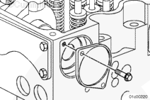










;)
;)
;)
;)
;)
;)
;)
;)
;)
;)
;)
;)
;)
;)
;)
;)
;)
;)
;)
;)
;)
;)
;)
;)
;)
;)
;)
;)
;)
;)
;)
;)
;)
;)
;)
;)
;)
;)
;)
;)
;)
;)
;)
;)
;)
;)
;)
;)
;)
;)
;)
;)
;)
;)
;)
;)
;)
;)
;)
;)
;)
;)
;)
;)
;)
;)
;)
;)
;)
;)
;)
;)
;)
;)
;)
;)
;)
;)
;)
;)
;)
;)
;)
;)
;)
;)
;)
;)
;)
;)
;)
;)
;)
;)
;)
;)
;)
;)
;)
;)
;)
;)
;)
;)
;)
;)
;)
;)
;)
;)
;)
;)
;)
;)
;)
;)
;)
;)