Centinel System – Repair Manual – 001-079   Gear Cover, Upper

Preparatory Steps

TOC

All Applications


  • Remove the water pump drive belt. Refer to Procedure 008-003.
  • Remove the alternator drive belt. Refer to Procedure 013-005.
  • Remove the fan hub assembly. Refer to Procedure 008-036.
  • Remove the breather tube and hose. Refer to Procedure 003-001.

SMALL | MEDIUM | LARGE

Remove

TOC

Automotive Applications


 WARNING 

The component weighs 23 kg [50 lb] or more. To reduce the possibility of injury, use a hoist or get assistance to lift the component.

Remove 16 capscrews and the upper gear cover.

Discard the strip seal.

SMALL | MEDIUM | LARGE
   

Industrial and Power Generation


Some industrial applications use a stamped steel cover with a clamping plate.

Remove two capscrews and install two guide pins.

Remove the 14 vibration isolator capscrew assemblies.

 
SMALL | MEDIUM | LARGE


 WARNING 

The component weighs 23 kg [50 lb] or more. To reduce the possibility of personal injury, use a hoist or get assistance to lift the component.

Remove the clamping plate and upper gear cover.

Discard the strip seal.

SMALL | MEDIUM | LARGE
   

Clean and Inspect for Reuse

TOC

All Applications


 WARNING 

Wear appropriate eye and face protection when using compressed air. Flying debris and dirt can cause personal injury.
 WARNING 

When using a steam cleaner, wear protective clothing and safety glasses, or a face shield. Hot steam can cause serious personal injury.
 WARNING 

When using solvents, acids, or alkaline materials for cleaning, follow the manufacturer’s recommendations for use. Wear goggles and protective clothing to reduce the possibility of personal injury.

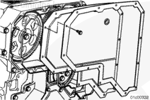
Use steam or solvent to clean the gear cover. Dry with compressed air.

SMALL | MEDIUM | LARGE


Clean the sealing surface on the rear face of the upper gear cover and the seal groove on the gear housing.

SMALL | MEDIUM | LARGE


Inspect the breather tube elbow and grommet. Refer to Procedure 003-001.

SMALL | MEDIUM | LARGE


Inspect the upper gear cover for cracks or damage.

If the cover is cracked, it must be replaced.

SMALL | MEDIUM | LARGE


Put the upper gear cover on a flat surface and inspect it for flatness.

SMALL | MEDIUM | LARGE


It is an acceptable practice to use a mallet to straighten an upper gear cover with minor bends.

If necessary, lay the gear cover on a flat surface and hit the upper gear to remove minor bends.

SMALL | MEDIUM | LARGE
   

Install

TOC

Automotive Applications


Install a new strip seal. Orient the overlap at the top and center of the gear housing.

Use a small amount of RTV at the overlap joint of the strip seal.

SMALL | MEDIUM | LARGE


 WARNING 

This component weighs 23 kg [50 lb] or more. To reduce the possibility of personal injury, use a hoist or get assistance to lift the component.

Install the cover with 16 capscrews.

SMALL | MEDIUM | LARGE


Tighten the capscrews in the sequence shown.

Torque Value:  28  n.m  [21 ft-lb]

SMALL | MEDIUM | LARGE
   

Industrial and Power Generation


Install a new strip seal. Orient the overlap at the top and center of the gear housing.

Use a small amount of RTV at the overlap joint of the strip seal.

SMALL | MEDIUM | LARGE


 WARNING 

This component weighs 23 kg [50 lb] or more. To reduce the possibility of personal injury, use a hoist or get assistance to lift the component.

Some industrial applications use a stamped steel cover with a clamping plate.

Install two guide pins in the gear housing.

Install the front gear cover over the guide pins.

Install the clamping plate, if used.

SMALL | MEDIUM | LARGE


Install 14 capscrews.

Remove the two guide pins and install the last two capscrews.

Tighten the capscrews in the sequence shown.

Torque Value:  28  n.m  [21 ft-lb]

SMALL | MEDIUM | LARGE
   

Finishing Steps

TOC

All Applications


  • Install the fan hub assembly. Refer to Procedure 008-036.
  • Install the water pump drive belt. Refer to Procedure 008-003.
  • Install the alternator drive belt. Refer to Procedure 013-005.
  • Install the breather tube and hose. Refer to Procedure 003-001.

SMALL | MEDIUM | LARGE
Last Modified:  29-Mar-2005