Centinel System – Repair Manual – 003-009   Rocker Lever Assembly

Preparatory Steps

TOC

Remove the engine brake solenoid valve wiring harness.

Remove the rocker lever cover. Refer to Procedure 003-011.

Remove the engine brake wiring harness. Refer to Procedure 020-015.

SMALL | MEDIUM | LARGE

Remove

TOC

There are four rocker lever shafts:

  • Front – valve and brake rocker lever shaft
  • Rear – valve and brake rocker lever shaft
  • Front – injector rocker lever shaft
  • Rear – injector rocker lever shaft.
 
SMALL | MEDIUM | LARGE


 CAUTION 

Some valves will not be loose. Do not tighten or bottom adjusting screw against lever. Engine damage can occur.

Loosen the valve and injector adjusting screw locknuts on each rocker lever.

Turn the adjusting screws counterclockwise until the rocker levers are loose.

 
SMALL | MEDIUM | LARGE


 CAUTION 

Use care when handling shafts. Rocker levers can fall off the shaft during removal and damage the levers.

Remove the valve and brake, rocker lever shaft capscrews, and the rocker lever shaft assemblies.

Remove the injector, rocker lever shaft capscrews, and the rocker lever shaft assemblies.

Remove the valve crossheads.

To prevent increased wear, mark each crosshead and rocker lever shaft assembly as it is removed so it can be installed back in its original location.

SMALL | MEDIUM | LARGE


Remove the rocker levers and brake levers from the shafts.

Remove the rocker lever spacers from the shaft.

Remove the locknuts and the adjusting screws from the rocker levers.

To prevent increased wear, mark each adjusting screw as it is removed so it can be installed back in its original rocker lever.

SMALL | MEDIUM | LARGE
   

Clean and Inspect for Reuse

TOC

 WARNING 

When using a steam cleaner, wear safety glasses or a face shield, as well as protective clothing. Hot steam can cause serious personal injury.
 WARNING 

When using solvents, acids, or alkaline materials for cleaning, follow the manufacturer’s recommendations for use. Wear goggles and protective clothing to reduce the possibility of personal injury.
 WARNING 

Some solvents are flammable and toxic. Read the manufacturer’s instructions before using.
 WARNING 

Wear appropriate eye and face protection when using compressed air. Flying debris and dirt can cause personal injury.

Use steam or solvent to clean the rocker lever shaft.

Dry with compressed air.

Be sure to blow out the oil passages.

SMALL | MEDIUM | LARGE


 WARNING 

When using a steam cleaner, wear safety glasses or a face shield, as well as protective clothing. Hot steam can cause serious personal injury.
 WARNING 

When using solvents, acids, or alkaline materials for cleaning, follow the manufacturer’s recommendations for use. Wear goggles and protective clothing to reduce the possibility of personal injury.
 WARNING 

Some solvents are flammable and toxic. Read the manufacturer’s instructions before using.
 WARNING 

Wear appropriate eye and face protection when using compressed air. Flying debris and dirt can cause personal injury.

Use steam or solvent to clean the valve crossheads, rocker lever adjusting screw, and nuts.

Dry with compressed air.

SMALL | MEDIUM | LARGE


Inspect the valve and brake rocker lever shaft for cracks or damage.

Measure the valve and brake rocker lever shaft outside diameter in the bushing wear area.

Valve and Brake Rocker Lever Shaft Outside Diameter
mm in
34.950 MIN 1.3760
35.000 MAX 1.3780

If the valve or brake rocker lever shaft is not within specifications, it must be replaced.

SMALL | MEDIUM | LARGE


Inspect the valve and brake rocker lever shaft for wear in the brake detent pockets.

A raised edge on one side of the detent pocket is normal and does not need replaced.

An elongated detent pocket, typically toward the cam follower end of the brake rocker lever, is excessive wear and must be replaced.

SMALL | MEDIUM | LARGE


Measure the injector rocker lever shaft outside diameter in the bushing wear area.

Injector Rocker Lever Shaft Outside Diameter
mm in
44.950 MIN 1.7697
45.000 MAX 1.7717

If the rocker lever shaft is not within specifications, it must be replaced.

SMALL | MEDIUM | LARGE


Inspect the rocker levers for cracks or unusual wear and thread condition.

SMALL | MEDIUM | LARGE


Measure the valve and brake rocker lever bushing bore inside diameter.

Valve and Brake Rocker Lever Bushing Bore Inside Diameter
mm in
35.037 MIN 1.3794
35.138 MAX 1.3834

If the valve or brake rocker lever bushing is not within specifications, the rocker lever must be replaced.

SMALL | MEDIUM | LARGE


Measure the injector rocker lever bushing bore inside diameter.

Injector Rocker Lever Bushing Bore Inside Diameter
mm in
45.037 MIN 1.7731
45.138 MAX 1.7771

If the injector rocker lever bushing is not within specifications, the rocker lever must be replaced.

SMALL | MEDIUM | LARGE


Inspect the valve crossheads and crosshead guide pins for damage.

SMALL | MEDIUM | LARGE


The contact area on the crossheads must be smooth with an even seating pattern.

If any distortions or cracks are found on the valve crossheads or adjusting screws, they must be replaced.

SMALL | MEDIUM | LARGE


Inspect the injector rocker lever adjusting screw socket for excessive wear.

If excessive wear is found, the injector rocker lever adjusting screw must be replaced.

SMALL | MEDIUM | LARGE


Measure the intake and exhaust valve adjusting screws for wear. Be sure the adjusting screw is perpendicular for measurement.

Intake and Exhaust Valve Adjusting Screw Length
mm in
46 MIN 1.81

SMALL | MEDIUM | LARGE


Measure the rocker lever spacers for wear.

Rocker Lever Spacer Width
mm in
11.5 MIN 0.453

If the rocker lever spacer is not within specification, it must be replaced.

SMALL | MEDIUM | LARGE
   

Install

TOC

Install the adjusting screw and locknut into each rocker lever. Do not tighten the locknuts.

SMALL | MEDIUM | LARGE


Install the injector rocker levers on the shaft.

Install the exhaust (1), intake (2), and engine brake (3) rocker levers onto the shaft.

SMALL | MEDIUM | LARGE


 WARNING 

Clear the rocker lever assembly mounting capscrew holes of oil and debris. Extensive engine damage can result if this warning instruction is not followed.

Install the valve crossheads.

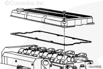
Position the valve/brake rocker lever assemblies onto the cylinder head.

SMALL | MEDIUM | LARGE


 CAUTION 

To reduce the possibility of valve rocker shaft damage due to inadequate brake rocker lever running clearance, follow the specified procedure to seat the valve rocker shafts on the cylinder head pedestals (1).

Each valve rocker shaft must be seated in the cylinder head pedestals prior to tightening the rocker shaft capscrews.

The front and rear rocker lever shaft assemblies will seat separately as the engine is rotated in the clockwise direction.

 
SMALL | MEDIUM | LARGE


Use the compressor drive or barring device to bar the engine over in the direction of rotation, clockwise as viewed from the front of the engine.

Align the A mark on the vibration damper with the timing mark on the gear cover.

SMALL | MEDIUM | LARGE


Either the front or the rear rocker shaft assembly will be fully seated on the cylinder head pedestals at this point.

Check the position of the front and rear valve rocker shaft assemblies to determine which one is fully seated.

Lubricate the capscrews of the fully seated rocker shaft with clean 15W-40 oil.

SMALL | MEDIUM | LARGE


 CAUTION 

To reduce the possibility of valve rocker shaft damage because of inadequate brake rocker lever running clearance, follow the specified capscrew torque procedure. The valve rocker lever shaft has a machined flat on the front of the shaft to provide proper brake rocker lever position. Therefore, the front rocker shaft capscrew (1) must be tightened first to control brake rocker lever position. Brake lever running clearance must always be checked after valve rocker lever shaft installation.

Check the brake running clearance. Refer to Procedure 003-004.

Tighten the front mounting capscrew for the fully seated valve rocker lever shaft to the initial torque value to locate the shaft.

Torque Value:  30  n.m  [22 ft-lb]

Tighten all the capscrews to the final torque value using the torque plus angle method. Tighten the capscrews from the center out.

Torque Value: Step 1 30 n.m   [22 ft-lb]
  Step 2 Rotate 60 degrees

SMALL | MEDIUM | LARGE


Use the compressor drive or barring device to bar the engine over in the direction of rotation, clockwise as viewed from the front of the engine.

Align the B mark on the vibration damper with the timing mark on the gear cover.

The remaining rocker shaft will be fully seated at this point.

Lubricate the capscrews of the fully seated rocker shaft with clean 15W-40 oil.

SMALL | MEDIUM | LARGE


 CAUTION 

To reduce the possibility of valve rocker shaft damage because of inadequate brake rocker lever running clearance, follow the specified capscrew torque procedure. The valve rocker lever shaft has a machined flat on the front of the shaft to provide proper brake rocker lever position. Therefore, the front rocker shaft capscrew must be tightened first to control brake rocker lever position. Brake lever running clearance must always be checked after valve rocker lever shaft installation.

Check the brake running clearance. Refer to Procedure 003-004.

Tighten the front mounting capscrew for the remaining valve rocker lever shaft to the initial torque value to locate the shaft.

Torque Value:  30  n.m  [22 ft-lb]

Tighten all the capscrews to the final torque value using the torque plus angle method. Tighten the capscrews from the center out.

Torque Value: Step 1 30 n.m   [22 ft-lb]
  Step 2 Rotate 60 degrees

SMALL | MEDIUM | LARGE


Position the injector rocker lever assemblies onto the cylinder head.

Lubricate the injector rocker lever shaft capscrews with clean 15W-40 oil. Install the capscrews and washers.

Tighten all the mounting capscrews.

Torque Value:  68  n.m  [50 ft-lb]
 
SMALL | MEDIUM | LARGE


Loosen capscrews one at a time 360° and tighten again, using the torque-plus-angle method. Tighten capscrews from center out.

Torque Value: Step 1 30 n.m   [22 ft-lb]
  Step 2 Rotate 60 degrees

Adjust the valve, injectors, and brake.

Refer to Procedure 003-004.

SMALL | MEDIUM | LARGE
   

Finishing Steps

TOC

Install the engine brake wiring harness. Refer to Procedure 020-015.

Install the rocker lever cover. Refer to Procedure 003-011.

Install the engine brake solenoid valve wiring harness.

SMALL | MEDIUM | LARGE
Last Modified:  22-May-2006