Early engine vibration dampers are marked with BRAKE SET 1-6, BRAKE SET 2-5, or BRAKE SET 3-4. The engine brakes must be set at the appropriate mark on these engines. Newer engine vibration dampers are marked with only A, B, or C, and are adjusted with the valves and injector on the same cylinder.
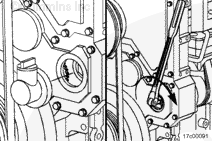
Locate the valve set marks on the outside of the vibration damper.
The set marks are A, B, and C:
Set to mark A to adjust cylinder 1 or 6.
Set to mark B to adjust cylinder 2 or 5.
Set to mark C to adjust cylinder 3 or 4.
Two complete revolutions are required to set all valves, engine brakes, and injectors.
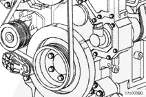
Do not pull or pry on the fan to manually rotate the engine. To do so can damage the fan blades. Damaged fan blades can cause premature fan failures which can result in serious personal injury or property damage.
The crankshaft rotation is clockwise, as viewed from the front of the engine.
The cylinders are numbered from the front of the engine (1-2-3-4-5-6).
The intake valve rocker lever is always the long lever on the valve rocker lever shaft.
Early engine vibration dampers are marked with BRAKE SET 1-6, BRAKE SET 2-5, or BRAKE SET 3-4. The engine brakes must be set at the appropriate mark on these engines. Newer engine vibration dampers are marked with only A, B, or C, and are adjusted with the valves and injector on the same cylinder.
The valves, brakes, and the injectors on the same cylinder are adjusted at the same index mark on the vibration damper.
NOTE: For illustrative purposes, position A is shown as the first step. It is not necessary to start with position A, as long as the proper sequence is followed.
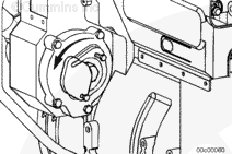
Use the compressor drive or barring device to bar the engine over in the direction of engine rotation, clockwise as viewed from the front of the engine. Align the A mark on the vibration damper with the pointer on the gear cover.
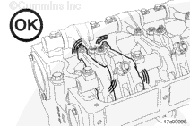
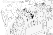
Check the valve rocker levers on the given cylinder to see if both intake and exhaust valves are closed.
Both sets of valves are closed when the rocker levers and the brake lever are loose. If both sets of valves are not closed, rotate the compressor drive gear one complete revolution, and align the A mark on the front damper with the pointer again.
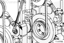
Use feeler gauges to measure the amount of clearance (lash) between the crosshead and the rocker lever nose. Measure and record the intake, exhaust, and brake valve lash. If the valve lash is not within the specifications listed below, the valve must be adjusted. See the adjust step in this procedure.
Press the brake lever down to verify the camshaft follower is in contact with the camshaft prior to measurement of the brake lash.
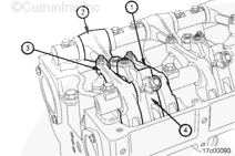
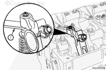
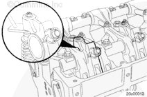
Rotate the brake lever to the detent (neutral) position. Check the clearance between the engine brake actuator piston and the cross head guide pin (1). If the brake running clearance is not within the specifications listed below, the running clearance must be adjusted. See the Adjust step in this procedure.
Brake Running Clearance
mm
in
0.635
MIN
0.025
2.79
MAX
0.110
Injector Lash
There is no service procedure to check the injector free load.
Batteries can emit explosive gases. To reduce the possibility of personal injury, always ventilate the compartment before servicing the batteries. To reduce the possibility of arcing, remove the negative (-) battery cable first and attach the negative (-) battery cable last.
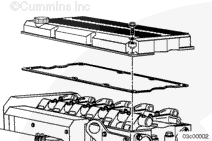
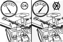
All overhead valve, injector, and brake adjustments must be made when the engine is cold (any stabilized coolant temperature at 60°C [140°F] or below).
Read the entire procedure for overhead adjustment before attempting to perform this operation.
Valves, injectors, and engine brakes (if equipped) must be correctly adjusted for the engine to operate efficiently. Valve, injector, and engine brake adjustment must be performed using the values listed in this section.
After an engine rebuild or any major repair where the injector and valve setting must be disturbed, set all of the valves, injectors, and brakes.
Early engine vibration dampers are marked with BRAKE SET 1-6, BRAKE SET 2-5, or BRAKE SET 3-4. The engine brakes must be set at the appropriate mark on these engines. Newer engine vibration dampers are marked with only A, B, or C, and are adjusted with the valves and injector on the same cylinder.
Locate the valve set marks on the outside of the vibration damper.
The set marks are A, B, and C:
Set to mark A to adjust cylinder 1 or 6.
Set to mark B to adjust cylinder 2 or 5.
Set to mark C to adjust cylinder 3 or 4.
Two complete revolutions are required to set all valves, engine brakes, and injectors.
Do not pull or pry on the fan to manually rotate the engine. To do so can damage the fan blades. Damaged fan blades can cause premature fan failures which can result in serious personal injury or property damage.
The crankshaft rotation is clockwise as viewed from the front of the engine.
The cylinders are numbered from the front of the engine (1-2-3-4-5-6).
The intake valve rocker lever is always the long lever on the valve rocker lever shaft.
Early engine vibration dampers are marked with BRAKE SET 1-6, BRAKE SET 2-5, or BRAKE SET 3-4. The engine brakes must be set at the appropriate mark on these engines. Newer engine vibration dampers are marked with only A, B, or C, and are adjusted with the valves and injector on the same cylinder.
The valves, brakes, and injectors on the same cylinder are adjusted at the same index mark on the vibration damper.
NOTE: For illustrative purposes, position A is shown as the first step. It is not necessary to start with position A, as long as the proper sequence is followed.
Use the compressor drive or barring device to bar the engine over in the direction of engine rotation, clockwise as viewed from the front of the engine. Align the A mark on the vibration damper with the pointer on the gear cover.
Check the valve rocker levers on the given cylinder to see if both intake and exhaust valves are closed.
Both sets of valves are closed when the rocker levers and the brake lever are loose. If both sets of valves are not closed, rotate the compressor drive gear one complete revolution, and align the A mark on the front damper with the pointer again.
Loosen the injector adjusting screw locknut on the cylinder.
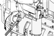
Do not use a click-type torque wrench.
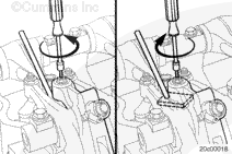
Use a dial-type torque wrench with a range of 0 to 150 in-lb to tighten the injector rocker lever adjusting screw. If the screw chatters during setting, repair the screw and lever as required.
Back out the adjusting screw one or two turns.
Hold the torque wrench in a position that allows you to look in a direct line at the dial. This is to make sure the dial will be read accurately.
Make sure the parts are aligned, and squeeze the oil out of the valve and injector train by tightening the adjusting screw.
Use this initial adjustment to preload the valve train and injector.
After setting the injector on a cylinder, set the valves and engine brakes on the same cylinder.
Early engine vibration dampers are marked with BRAKE SET 1-6, BRAKE SET 2-5, or BRAKE SET 3-4. The engine brakes must be set at the appropriate mark on these engines. Newer engine vibration dampers are marked with only A, B, or C, and are adjusted with the valve and injector on the same cylinder.
With the set mark aligned with the pointer on the gear cover and both sets of valves closed on the cylinder, loosen the locknuts on the intake and exhaust valve adjusting screws.
Use the compressor drive or barring device to bar the engine over in the direction of rotation, clockwise as viewed from the front of the engine. Align the A mark on the vibration damper with the pointer on the gear cover.
For illustrative purposes, position A is shown as the first step. It is not necessary to start with position A, as long as the proper sequence is followed.
Check the valve rocker levers on the given cylinder to see if both intake and exhaust valves are closed.
Both sets of valves are closed when the rocker levers and the brake lever are loose. If both sets of valves are not closed, rotate the compressor drive gear one complete revolution, and align the A mark on the front damper with the pointer again.
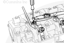
Loosen the locknut on the brake lever adjusting screw, and back out the adjusting screw one turn.
Insert the feeler gauge, Part Number 3163530, between the bottom of the engine brake piston and the top of the exhaust valve pin on the exhaust valve crosshead.
Tighten the adjusting screw until drag on the feeler gauge is felt. Proper drag means that there is no motion of the brake lever camshaft follower against the cam lobe.
Engine damage can occur if the running clearance is not within specifications.
Check the running clearance:
Rotate the engine brake rocker lever to the detente (neutral) position.
Check the clearance (1) between the engine brake lever actuator piston and the crosshead guide pin.
Engine Brake Rocker Lever Running Clearance
mm
in
0.635
MIN
0.025
2.790
MAX
0.110
If the running clearance does not meet specification, loosen, but do not remove the rocker shaft capscrews, and rotate the shaft in the direction required to bring the running clearance within the listed specification. It is critical that this clearance be set and verified on all six brake levers. Engine damage can result if this task is not completed.
Check the brake running clearance.
The rocker lever shafts must be adjusted so that all three engine brake levers fall within the given running clearance specification.
Repeat the process to adjust all injectors, engine brakes, and valves according to the chart shown below.
Batteries can emit explosive gases. To reduce the possibility of personal injury, always ventilate the compartment before servicing the batteries. To reduce the possibility of arcing, remove the negative (-) battery cable first and attach the negative (-) battery cable last.
Hello, I'm Jack, a diesel engine fan and a blogger. I write about how to fix and improve diesel engines, from cars to trucks to generators. I also review the newest models and innovations in the diesel market. If you are interested in learning more about diesel engines, check out my blog and leave your feedback.
View all posts by Jack


 WARNING
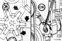


 CAUTION
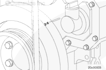

;)
;)
;)
;)
;)
;)
;)
;)
;)
;)
;)
;)
;)
;)
;)
;)
;)
;)
;)
;)
;)
;)
;)
;)
;)
;)
;)
;)
;)
;)
;)
;)
;)
;)
;)
;)
;)
;)
;)
;)
;)
;)
;)
;)
;)
;)
;)
;)
;)
;)
;)
;)
;)
;)
;)
;)