NOTE: If the threaded hole adjacent to the dowel pin is selected, the dowel pin must be removed prior to drilling.
In most instances, this procedure is easiest to perform when staring with a threaded hole near the 12 o’clock position.
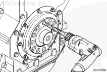
Use a 12.7-mm [1/2-in] drill bit, Part Number 4918535 or equivalent, to ream out the threaded hole so the 6.35-mm [1/4-in] bushing, Part Number 4918538 or equivalent, will insert easily.
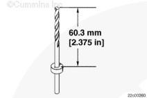
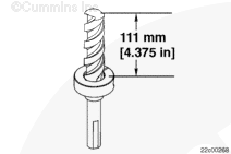
Install the stop collar, Part Number 4918541 or equivalent, onto a 6.35-mm [1/4-in] drill bit, Part Number 4918533 or equivalent, at a depth of 60.3 mm [2.375 in].
Install the stop collar, Part Number 4918542 or equivalent onto a 12.7-mm [1/2-in] drill bit, Part Number 4918535 or equivalent, at a depth of 54 mm [2.125 in].
Wear appropriate eye and face protection when using compressed air. Flying debris and dirt can cause personal injury.
CAUTION
Do not drill holes completely through the crankshaft adapter or gear. Damage to the engine, crankshaft, and or tools can occur.
The use of a generous amount of cutting fluid will increase tool life and ease the drilling operation.
A maximum drill speed of 850 rpm is recommended.
Remove the 6.35-mm [1/4-in] drill bushing, Part Number 4918538 or equivalent. Using the previously drilled 6.35-mm [1/4-in] hole as a pilot, drill a 12.7-mm [1/2-in] hole to the preset depth.
Clean out the debris using low pressure air and a shop towel to cover the hole as necessary.
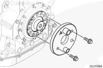
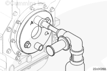
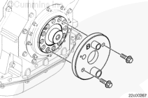
Install the drill guide adapter, Part Number 4918276, onto the crankshaft nose so the drill guide bushing labeled “A” is aligned with the previously drilled 21.7-mm [1/2-in] hole.
Install and tighten 2 existing damper capscrews through the drill guide adapter.
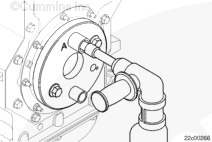
Remove the drill guide adapter from the crankshaft and rotate the drill guide adapter 180 degrees so the drill guide bushing labeled “B” is aligned with the previously drilled hole.
Install and tighten 2 existing damper capscrews through the drill guide adapter.
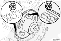
Inspect the crankshaft, tone wheel, and crankshaft gear for damage.
Inspect the machined surface for scratches or nicks.
Use a crocus cloth to remove the scratches or nicks. If scratches or nicks can be felt with a fingernail after the crankshaft has been polished with the crocus cloth, the crankshaft must be replaced.
To reduce the possibility of personal injury, wear protective gloves when handling parts that have been heated.
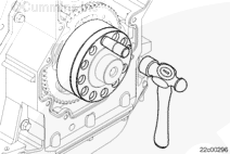
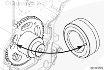
NOTE: During the installation of the crankshaft adapter, the pin located on the backside of the crankshaft adapter must align with the slot on the front surface of the tone wheel.
Do not lubricate the crankshaft prior to installing the crankshaft adapter.
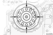
To check the installation, attempt to insert a 0.25-mm [0.010-in] feeler gauge between the crankshaft gear and the tone wheel at 4 locations approximately 90 degrees apart.
If the feeler gauge can be inserted, the tone wheel must be removed and replaced.
NOTE: If the timing pin, Part Number 3163020, can not be inserted when the damper marking “Insert Pin” is aligned with the marking on the lower gear, the tone wheel or crankshaft adapter is not properly aligned with the crankshaft.
NOTE: It will be necessary to remove the lower gear cover, crankshaft seal, and vibration damper and check for missing dowel pins and or misalignment in the crankshaft adapter or tone wheel.
Install the radiator, charge air cooler, and the hood, if applicable. Refer to the OEM service manual.
Hello, I'm Jack, a diesel engine fan and a blogger. I write about how to fix and improve diesel engines, from cars to trucks to generators. I also review the newest models and innovations in the diesel market. If you are interested in learning more about diesel engines, check out my blog and leave your feedback.
View all posts by Jack
 CAUTION



 WARNING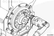







;)
;)
;)
;)
;)
;)
;)
;)
;)
;)
;)
;)
;)
;)
;)
;)
;)
;)
;)
;)
;)
;)
;)
;)
;)
;)
;)
;)
;)
;)
;)
;)
;)
;)
;)
;)
;)
;)
