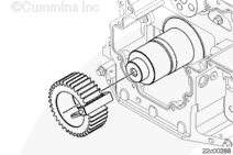
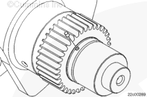
Centinel System – Repair Manual – 001-018   Crankshaft Gear, Front (Crankshaft Installed)

View Related Topic


Preparatory Steps

TOC

On-Engine Repair


 WARNING 

Batteries can emit explosive gases. To reduce the possibility of personal injury, always ventilate the compartment before servicing the batteries. To reduce the possibility of arcing, remove the negative (-) battery cable first and attach the negative (-) battery cable last.

SMALL | MEDIUM | LARGE

Remove

TOC

 WARNING 

Wear appropriate eye and face protection when using compressed air. Flying debris and dirt can cause personal injury.
 CAUTION 

Protect the engine internals from debris generated during the drilling operation. Mask the engine internals using tape, plugs, and or shields to prevent debris from entering the engine internals. Failure to do this will result in significant engine damage.

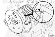
Install the plastic drill guide, Part Number 4918547, with the “FRONT” facing the operator. Align the slot with the crankshaft gear tooth root.

SMALL | MEDIUM | LARGE


Install the stop collar, Part Number 4918541 or equivalent, onto a 6.35-mm [0.250-in] drill bit at a depth of 111 mm [4.375 in].

SMALL | MEDIUM | LARGE


Tool life will be extended if the drill bit does
not break through the back of the crankshaft gear.

The use of a generous amount of cutting fluid will increase tool life and ease the drilling operation.

Drill a 6.35-mm [0.250-in] pilot hole to the preset depth.

Clean out the debris. Use low pressure air and a shop towel to cover the hole as necessary.

 
SMALL | MEDIUM | LARGE


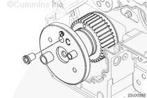
Install the large drill guide adapter, Part Number 4918276, onto the crankshaft nose with the hole labeled “C” aligned with the pilot hole.

SMALL | MEDIUM | LARGE


Use the alignment pin, Part Number 4918577, to align the guide with the hole.

Tighten the 7.94-mm [5/16-in] set screw to hold the guide to the crankshaft.

SMALL | MEDIUM | LARGE


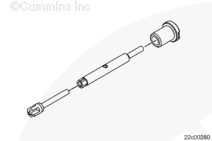
Install the countersink cutter, Part Number 4918578 or equivalent, into a 102-mm [4-in] extension, Part Number 4918544 or equivalent.

Slide the 11.5-mm [29/64-in] drill bushing, Part Number 4918534 or equivalent, onto the shaft.

Install the assembly and lock the 11.5-mm [29/64-in] drill bushing into the hole labeled “C”.

SMALL | MEDIUM | LARGE


Countersink the pilot hole until the outside diameter of the countersink is approximately 1.6 to 3.2 mm [1/16 to 1/8 in] deep.

Clean out the debris. Use low pressure air and a shop towel to cover the hole as necessary.

Remove the countersink and the drill bushing.

SMALL | MEDIUM | LARGE


Insert the drill bushing, Part Number 4918539, or equivalent, into the hole labeled “C” and lock the 12.7-mm [1/2-in] drill bushing into the drill guide.

SMALL | MEDIUM | LARGE


The use of a generous amount of cutting fluid will increase tool life and ease the drilling operation.

Drill a 12.7-mm [1/2-in] hole to depth of the previously 6.35-mm [1/4-in] drilled hole.

Clean out the debris. Use low pressure air and a shop towel to cover the hole as necessary.

Remove the tone wheel alignment dowel from the crankshaft.

SMALL | MEDIUM | LARGE


Install the locating gauge, Part Number 4918314, or other suitable spacer, onto the crankshaft gear.

A spacer
must be installed or the crankshaft will be damaged during the crankshaft gear removal.

SMALL | MEDIUM | LARGE


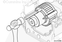
Insert the small splitting wedge, Part Number 4918545, with the flatted area facing toward the crankshaft and into the drilled hole.

SMALL | MEDIUM | LARGE


Strike the small splitting wedge with a suitable hammer until the crankshaft gear splits.

Remove the crankshaft gear by hand or use a suitable puller if necessary.

SMALL | MEDIUM | LARGE
   

Clean and Inspect for Reuse

TOC

 WARNING 

When using solvents, acids or alkaline materials for cleaning, follow the manufacturer’s recommendations for use. Wear goggles and protective clothing to reduce the possibility of personal injury.
 WARNING 

Wear appropriate eye and face protection when using compressed air. Flying debris and dirt can cause personal injury.

NOTE: If scratches or nicks can be felt with a fingernail after the crankshaft has been polished with a crocus cloth, the crankshaft
must be replaced.

Inspect the crankshaft for damage.

Inspect the machined surface for scratches or nicks.

SMALL | MEDIUM | LARGE
   

Install

TOC

Install the locating gauge, Part Number 4918314, onto the side of crankshaft gear.

Heat the crankshaft gear for 3 hours at 177°C [350°F] before attempting the installation.

SMALL | MEDIUM | LARGE


 WARNING 

To reduce the possibility of personal injury, wear protective gloves when handling parts that have been heated.

NOTE: The crankshaft gear
must be installed within 15 seconds after being removed from the oven.

Install the crankshaft gear until the locating gauges make contact with the front crankshaft journal.

Hold the crankshaft gear in position for approximately 60 seconds to allow the shrink fit to properly hold the components.

Remove the locating gauge from the crankshaft gear.

SMALL | MEDIUM | LARGE


Use a brass hammer, tap the alignment dowel pin in the crankshaft hole until the alignment dowel pin bottoms out.

Check the gap between the crankshaft gear and the crankshaft first journal by inserting the locating gauge, Part Number 4918314.

If the locating gauge is loose or can
not be inserted, replace the crankshaft gear.

SMALL | MEDIUM | LARGE
   

Finishing Steps

TOC

 WARNING 

Batteries can emit explosive gases. To reduce the possibility of personal injury, always ventilate the compartment before servicing the batteries. To reduce the possibility of arcing, remove the negative (-) battery cable first and attach the negative (-) battery cable last.

SMALL | MEDIUM | LARGE
Last Modified:  17-Jun-2009