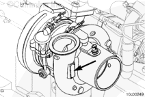
Before beginning this repair, check the turbocharger serial number on the turbocharger data plate.
This repair procedure applies to ISX CM870 variable geometry turbochargers with serial numbers less than C060306601. Do NOT perform this repair if the turbocharger serial number is C060306601 or greater.
This repair is recommended only for ISX CM870 variable geometry turbochargers built with aluminum compressor impellers.
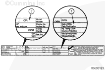
ISX CM870 CPL 8283 or 8284 (530 to 565 horsepower) engines built between 01-November-2002 and 31-December-2003 were built with variable geometry turbochargers that have a titanium impeller. Before beginning this repair, check the engine manufacture date (1) and CPL (2) on the engine data plate. Do NOT perform the repair if the CPL is 8283 or 8284 and the engine manufacture date is between 01-November-2002 and 31-December-2003.
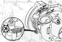
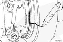
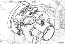
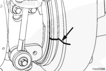
Inspect the turbocharger at the variable geometry actuator cross shaft lever arm for an oil leak.
If oil is leaking from under the cross shaft lever arm where the cross shaft enters the bearing housing, the oil seal, cross shaft bushing, and cross shaft must be replaced.
Start with the Steam Cleaning section to begin the seal, bushing, and cross shaft replacement.
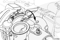
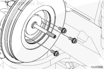
Create an alignment mark on the turbocharger compressor housing, bearing housing, and v-band clamp. This mark will make certain the components are oriented correctly during assembly.
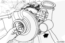
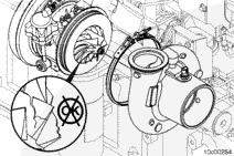
NOTE: Use care when removing the turbocharger compressor housing so the housing does not contact the impeller blades. Turbocharger compressor impeller blades can easily be damaged, which can lead to performance complaints.
Use a soft hammer to tap the turbocharger compressor housing away from the bearing housing. Tap the turbocharger compressor housing around the outside diameter. Turn the turbine impeller while tapping to be sure the housing is not binding the turbocharger compressor impeller and shaft.
NOTE: A wedge type tool may be required to separate the compressor housing from the bearing housing, but be sure the wedge tool does not damage the compressor or bearing housing joint.
Once the turbocharger compressor housing is removed, visually inspect the impeller blades for damage. If the blades are damaged, the turbocharger must be replaced.
Remove the turbocharger compressor housing v-band clamp.
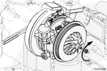
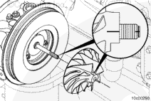
This mark is required during the installation of the compressor impeller, so the turbocharger shaft and impeller retains its balance after assembly. Failure to mark the turbocharger shaft and impeller for alignment can cause turbocharger imbalance, which can result in a performance complaint by the operator.
Before loosening the compressor impeller nut, create an alignment mark on the compressor impeller and the end of the compressor shaft.
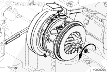
To avoid damaging the turbocharger shaft, do not apply too much side load on the turbocharger shaft while loosening the impeller nut. The turbocharger compressor impeller shaft and nut have LEFT HAND threads. The impeller nut must be removed correctly to prevent damage to the turbocharger shaft.
Use a 12-point socket on the turbine side of the turbocharger to hold the shaft stationary.
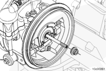
Loosen the turbocharger compressor impeller nut by turning the nut clockwise. Then remove the nut from the turbocharger shaft.
When using a heat gun, wear protective gloves to prevent personal injury from hot components.
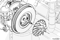
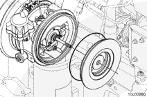
Remove the compressor impeller from the shaft.
NOTE: If the compressor impeller hangs on the shaft, heat the impeller for 2 minutes with a heat gun, while rotating the impeller from the turbine side of the turbocharger. If the impeller can not be removed, the turbocharger must be replaced to repair the oil leak from under the cross shaft lever arm.
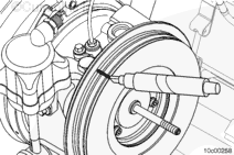
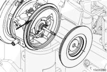
Create an alignment mark on the diffuser plate and the bearing housing. This will aid in the correct orientation of the diffuser plate during assembly.
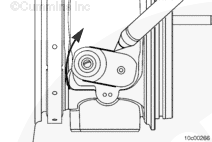
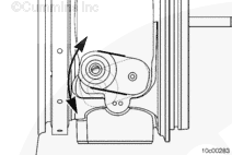
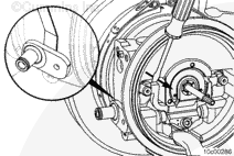
Rotate the cross shaft clockwise, by hand, to the end of the cross shaft travel.
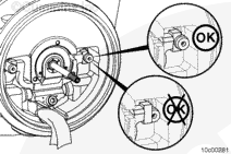
Create clearly visible marks onto the bearing housing along both sides of the cross shaft lever arm. These marks are required to correctly align the replacement cross shaft during assembly.
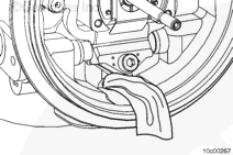
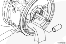
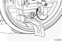
Plug the turbocharger lubricating oil drain hole in the bearing housing with a clean lint free cloth to prevent items from falling into the turbocharger oil drain line.
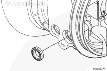
Use care not to damage the bearing housing bore when removing the bushing.
Use the bushing replacer tool to remove the variable geometry actuator cross shaft bushing from the bearing housing. Gently tap the bushing all the way through the bore and remove it from the inside of the bearing housing.
To avoid damage to the bushing during installation, do not tap the end of the bushing at an angle. Excessive side load will result if the bushing is tapped at an angle.
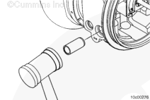
Orient the replacement bushing to install the chamfered end into the bore.
Next, gently tap the bushing with a soft hammer to start the bushing squarely into the bore.
Tap the bushing squarely on the end to install the bushing as far as possible, without contacting the face of the bearing housing with the soft hammer.
To avoid damage to the bushing during installation, do not tap the end of the bushing replacer at an angle. Excessive side load will result if the bushing replacer is tapped at an angle.
Use the bushing replacer and the small installer plate.
Tap the bushing replacer squarely on the end to install the replacement bushing until the installer plate contacts the bottom of the counterbore in the bearing housing.
An oil leak will result if the new seal is not oriented correctly and installed properly.
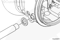
Install the stepped installer plate onto the bushing replacer.
Install the seal onto the end of the bushing replacer. Orient the replacement seal so the rubber coated face of the seal contacts the step on the installer plate and the steel carrier outer diameter is pointed toward the seal bore in the bearing housing.
Align the seal with the bore in the bearing housing. Gently tap the bushing replacer until the stepped installer plate bottoms out on the face of the bearing housing.
Install the pivot blocks on each side of the yoke. Orientation of the pivot blocks is not required.
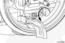
NOTE: Be sure the turbocharger oil drain hole in the bearing housing is plugged with a clean lint free cloth to prevent items from falling into the turbocharger oil drain line.
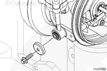
Install a replacement mounting Allen™ head capscrew through the clearance hole into the threads at the bottom of the yoke. Do not torque at this time.
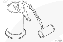
Apply additional clean engine lubricating oil to the cross shaft.
Slide the cross shaft into the yoke, with one hand, while holding the yoke in place with the opposite hand. Slide the shaft all the way through the yoke and into the rear bushing.
Do not over tighten the yoke mounting capscrew. Damage to the yoke will result.
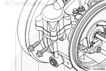
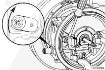
With the yoke position fixed and the cross shaft lever arm aligned with the alignment marks, torque the yoke capscrew.
Torque Value: 37 n.m [27 ft-lb]
Remove the 0.76 mm [0.030 in] shim.
Check the cross shaft orientation to verify the lever arm is still aligned with the alignment marks. Proper cross shaft lever arm alignment is required for proper turbocharger operation.
Use care during assembly to prevent damage to the sealing ring or the oil slinger bore.
If the oil slinger was removed separately, install the oil slinger into the diffuser plate. Be sure the slinger is oriented with the sealing ring gap (1) facing upward.
A small amount of clean engine lubricating oil can be used on the oil slinger.
Install three replacement Allen™ head capscrews and washers finger tight. Tighten all capscrews to the initial torque specification before tightening to the final torque specification.
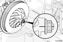
To avoid damaging the turbocharger shaft, do not apply too much side load on the turbocharger shaft while tightening the nut. The turbocharger compressor impeller shaft and nut have LEFT HAND threads. The nut must be installed correctly to prevent damage to the turbocharger shaft.
Install the nut and tighten. Use a 12-point socket on the turbine side of the turbocharger to hold the shaft from rotating.
Turn the nut counterclockwise to tighten. The nut and shaft have left hand threads.
NOTE: Use care when installing the turbocharger compressor housing, so the housing does not contact the impeller blades. Turbocharger compressor impeller blades can easily be damaged, which can lead to performance complaints.
Lubricate the inside mounting flange of the compressor housing with clean engine lubricating oil prior to installation.
Install the compressor housing squarely onto the bearing housing. Use a soft hammer to tap around the outside diameter of the compressor housing.
Hello, I'm Jack, a diesel engine fan and a blogger. I write about how to fix and improve diesel engines, from cars to trucks to generators. I also review the newest models and innovations in the diesel market. If you are interested in learning more about diesel engines, check out my blog and leave your feedback.
View all posts by Jack

 WARNING


 CAUTION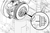


















;)
;)
;)
;)
;)
;)
;)
;)
;)
;)
;)
;)
;)
;)
;)
;)
;)
;)
;)
;)
;)
;)
;)
;)
;)
;)
;)
;)
;)
;)
;)
;)
;)
;)
;)
;)
;)
;)
;)
;)
;)
;)
;)
;)
;)
;)
;)
;)
;)
;)
;)
;)
;)
;)
;)
;)
;)
;)
;)
;)
;)
;)
;)
;)
;)
;)
;)
;)
;)
;)
;)
;)
;)
;)
;)
;)
;)
;)
;)
;)
;)
;)
;)
;)
;)
;)
;)
;)
;)
;)
;)
;)
;)
;)
;)
;)
;)
;)
;)
;)
;)
;)
;)
;)
;)
;)
;)
;)