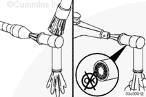
NOTE: Brush away any loose dirt from around the area of air handling connections to avoid contamination of the interior of the engine.
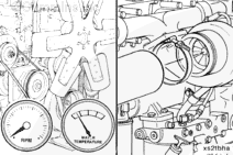
Shut off the engine.
Allow the turbocharger to cool.
Remove the intake piping and compressor discharge piping. Cover the openings in the pipes with caps from the Air Handling and Vehicle Air Plumbing Clean Care Kits, Part Numbers 4919403, and 4919425 respectively.
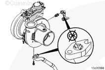
Use a high-intensity black light, Part Number 3163337 (100 watt), or equivalent, or Part Number 3163338 (50 watt), or equivalent, to inspect the compressor intake and discharge for signs of oil.
If oil is present in the compressor intake, as well as the discharge, check upstream of the turbocharger for the source of the oil.
If oil is present only in the discharge side, check for intake restriction.
If no intake restriction is found, replace the turbocharger.
Coolant is toxic. Keep away from children and pets. If not reused, dispose of in accordance with local environmental regulations.
WARNING
Do not remove the pressure cap from a hot engine. Wait until the coolant temperature is below 50°C [120°F] before removing the pressure cap. Heated coolant spray or steam can cause personal injury.
If the pressure decreases greater than 34 kPa [5 psi] in 1 minute, use a spray bottle of soapy water to wet all hose connections. Bubbles will appear if the connections are leaking.
If the pressure does decrease excessively, and the hose connections are not leaking, replace the turbocharger.
Coolant is toxic. Keep away from children and pets. If not reused, dispose of in accordance with local environmental regulations.
WARNING
Do not remove the pressure cap from a hot engine. Wait until the coolant temperature is below 50°C [120°F] before removing the pressure cap. Heated coolant spray or steam can cause personal injury.
Disconnect the turbocharger speed sensor. For Signature™ and ISX engines, see the following procedure in the Troubleshooting and Repair Manual, CM870 Electronic Control System Signature™ and ISX Engines, Bulletin 4021334. Refer to Procedure 019-390 in Section 19.
Disconnect the turbocharger compressor air inlet temperature sensor. For ISX engines, see the following procedure in the Troubleshooting and Repair Manual, CM870 Electronic Control System Signature™ and ISX Engines, Bulletin 4021334.Refer to Procedure 019-395 in Section 19.
Coolant is toxic. Keep away from children and pets. If not reused, dispose of in accordance with local environmental regulations.
WARNING
Do not remove the pressure cap from a hot engine. Wait until the coolant temperature is below 50°C [120°F] before removing the pressure cap. Heated coolant spray or steam can cause personal injury.
NOTE: Brush away any loose dirt from around the area of the air handling connections to avoid contamination of the interior of the engine.
Disconnect the turbocharger speed sensor. For ISX and ISM engines, see the following procedure in the ISX CM871 and ISM CM876 Electronic Control System, Troubleshooting and Repair Manual, Bulletin 4021560. Refer to Procedure 019-390 in Section 19.
Disconnect the turbocharger compressor air inlet temperature sensor. For ISX and ISM engines, see the following procedure in the ISX CM871 and ISM CM876 Electronic Control System, Troubleshooting and Repair Manual, Bulletin 4021560. Refer to Procedure 019-395 in Section 19.
Remove the charge-air piping. Use protective caps from the Air Handling Clean Care Kit, Paart Number 4919403. to cover open points.
Remove the turbocharger air inlet piping. Use protective caps from the Air Handling and Vehicle Air Plumbing Clean Care Kits, Part Numbers 4919403, and 4919425 respectively to cover open points.
Disconnect the aftertreatment adapter pipe. Use protective cap from the Air Handling Clean Care Kit, Part Numbers 4919403 and 4919425 respectively, to cover the turbocharger exhaust outlet.Refer to Procedure 011-043 in Section 11.
NOTE: In some applications, the turbocharger will not clear the lubricating oil cooler assembly during removal and installation. It will, perhaps, be necessary to remove the exhaust manifold and turbocharger together, and then separate the two components. If the two components must be removed together for the removal and installation of the exhaust manifold. Refer to Procedure 011-007 in Section 11.
If the turbocharger mounting nuts do not loosen freely, split the nuts to avoid breaking a mounting stud.
This component weighs 23 kg [50 lb] or more. To reduce the possibility of personal injury, use a hoist or get assistance to lift this component.
CAUTION
When installing a lifting eye, be sure the shoulder of the lifting eye is bottomed against bearing housing. Failure to do so can result in failure of the lifting eye and personal injury.
CAUTION
If the lifting eye is installed in the turbocharger bearing housing, it is to be used exclusively for turbocharger removal and installation. It is not to be used in removal of the exhaust manifold, or engine. Doing so will cause damage to the turbocharger.
Remove the oil supply and the oil drain tube from the turbocharger.
This component weighs 23 kg [50 lb] or more. To reduce the possibility of personal injury, use a hoist or get assistance to lift this component.
Thread a lifting strap around the turbocharger bearing housing. Take care not to bend the coolant lines when lifting the turbocharger.
Care must be taken not to damage the turbocharger compressor inlet air temperature sensor, the turbocharger speed sensor, and the turbocharger actuator coolant lines when removing the turbocharger.
Remove the four turbocharger mounting nuts.
NOTE: If the turbocharger mounting nuts do not loosen freely, split the nuts to avoid breaking a mounting stud.
Cover the turbocharger exhaust inlet port with heavy tape or a protective cap from the Air Handling and the Vehicle Air Plumbing Clean Care Kit, Part Numbers 4919403 and 4919425 respectively. Cover the opening on the exhaust manifold with heavy tape.
If the turbocharger is being replaced with a new turbocharger, remove the variable geometry turbocharger actuator.
Turbine Housing Replacement for ISX Automotive with CM570, QSX15 with CM570, and Power Generation with CM570
Place the turbocharger outlet on a clean flat surface. Create an alignment mark on the turbine housing, bearing housing and the V-band clamp. This mark will make certain the components are oriented correctly during the assembly process.
NOTE: This procedure applies ONLY to Automotive with CM570, QSX15 with CM570, and Power Generation with CM570. Do NOT disassemble variable geometry turbochargers (VGT).
Turbine blades can be easily damaged and care is required for the turbine housing removal process.
Use a soft hammer to tap the turbine housing down against a soft bench surface.
As the bearing housing and compressor housing assembly loosen, gently lift the assembly out of the turbine housing.
Wastegate mounting is not affected by this disassembly process.
Always clean the turbine housing before assembly, paying particular attention to the surface close to the turbine housing and the bearing housing location.
Turbine Housing Cleaning for ISX Automotive with CM570, QSX15 with CM570, and Power Generation with CM570
The turbocharger turbine housing surface adjacent to the turbine compressor wheels must be clean, smooth, and free from deposits.
Inspect the components to detect signs of burning and other conditions, in order to obtain as much information as possible before washing.
NOTE: This procedure applies ONLY to Automotive with CM570, QSX15 with CM570, and Power Generation with CM570. Do NOT disassemble variable geometry turbochargers (VGT).
Cracking in the turbine housing inlet flange and the inlet duct generally requires replacement of the turbine housing. Acceptance and rejection guidelines are shown in these illustrations. If an exhaust gasket is available, always make certain that cracks do not exist within the sealing area.
Check the turbine housing inlet flange flatness. It must be within 0.1 mm [0.004 in] to be acceptable for reuse.
If the engine experiences a turbocharger malfunction or any other occasion where oil or debris is put into the charge-air system, the charge-air system must be inspected and cleaned. Refer to Procedure 010-027 in Section 10.
Inspect the turbocharger compressor v-band outlet and the discharge elbow v-band connection for dents or fretting.
Replace the turbocharger or discharge elbow, if damaged, to prevent compressed air leaks.
Inspect the compressor wheel for signs of rubbing against the compressor cover. Replace the turbocharger if rubbing evidence is seen.
Use light finger pressure to push the compressor wheel. If the compressor wheel contacts the cover, replace the turbocharger.
If the engine experiences a turbocharger malfunction or any other occasion where oil or debris is put into the charge-air system, the charge-air system must be inspected and cleaned. Refer to Procedure 010-027 in Section 10.
NOTE: All openings on the turbocharger, including the turbine inlet connection, must be plugged with caps from the Air Handling and Vehicle Air Plumbing Clean Care Kits, Part Numbers 4919403, and 4919425 respectively, during flange cleaning.
Clean the turbocharger and exhaust manifold where the retaining nut contacts the turbocharger and exhaust manifold.
Clean the mating surfaces with Scotch-Brite™ 7448 abrasive pad.
After abrasive cleaning, wipe debris from both surfaces with a clean shop towel.
The surface under the mounting nuts must be free of dirt, rust, or any other debris, before applying anti-seize compound, Part Number 3823097.
Inspect the turbocharger compressor v-band outlet and the discharge elbow v-band connection for dents or fretting.
Replace the turbocharger or discharge elbow, if damaged, to prevent compressed air leaks.
Inspect the compressor wheel for signs of rubbing against the compressor cover. Replace the turbocharger if rubbing evidence is seen.
Use light finger pressure to push the compressor wheel. If the compressor wheel contacts the cover, replace the turbocharger.
If the engine experiences a turbocharger malfunction or any other occasion where oil or debris is put into the charge-air system, the charge-air system must be inspected and cleaned. Refer to Procedure 010-027 in Section 10.
ISX Automotive with CM570, QSX15 with CM570 and Power Generation with CM570
To install the turbine housing, position the V-band clamp over the bearing housing and align the ink marks applied during the disassembly process.
Apply anti-seize compound to the bearing housing locating bore of the turbine housing.
Carefully slide the bearing and compressor housing assembly into the turbine housing. Use the ink alignment mark to locate the turbine housing assembly in the correct orientation with the turbine housing.
This component weighs 23 kg [50 lb] or more. To reduce the possibility of personal injury, use a hoist or get assistance to lift this component.
NOTE: If the exhaust manifold and turbocharger were removed together in order for the turbocharger to clear the lubricating oil cooler assembly, see the following procedure for installation of the exhaust manifold. Refer to Procedure 011-007 in Section 11.
Install a new mounting gasket, the turbocharger, and the four mounting nuts.
Tighten the mounting nuts.
Torque value for the standard nut:
Torque Value: 61 n.m [45 ft-lb]
Torque value for the Spiralock™ nut (identified by “SPL” on the nut flange):
Proper routing of the turbocharger oil supply tube is critical to prevent failure. Avoid any tube-to-metal contact. (The inlet supply fitting must be oriented slightly off vertical to allow proper alignment.)
If installing a new turbocharger, make sure the turbocharger is aligned, loosen the compressor and turbine v-bands, and adjust as needed. Tighten the v-bands.
Torque Value: 9 n.m [80 in-lb]
Torque Value: 12 n.m [106 in-lb]
If installing a new turbocharger, install the male union elbow.
Torque Value: 30 n.m [22 ft-lb]
Install the turbocharger oil supply tube on the elbow.
This component weighs 23 kg [50 lb] or more. To reduce the possibility of personal injury, use a hoist or get assistance to lift this component.
CAUTION
When installing lifting eye, be sure the shoulder of the lifting eye is bottomed against bearing housing. Failure to do so can result in failure of lifting eye and personal injury.
CAUTION
If a lifting eye is installed in turbocharger bearing housing, it is to be used exclusively for turbocharger removal and installation. It is not to be used in removal of the exhaust manifold, or engine. Doing so will cause damage to the turbocharger.
CAUTION
Do not rotate the turbocharger turbine housing. Loosening turbine v-band and rotating the turbine housing can cause damage to internal variable geometry mechanism.
The capscrew in the top of the turbocharger bearing housing can be removed and replaced with a lifting eye to aid in the installation of the turbocharger.
Install a new gasket, the turbocharger, and the four mounting nuts. Tighten the mounting nuts.
Apply a film of high-temperature anti-seize compound, Part Number 3823097, or equivalent, to the turbocharger mounting studs and to the flange area on the retaining nuts. Properly applying anti-seize compound will reduce the possibility of the nuts loosening over time.
If installing a new turbocharger, install the coolant and oil fittings into the bearing housing.
NOTE: Use a ratchet and deepwell socket to install these fittings.
Torque Value: 30 n.m [22 ft-lb]
CAUTION
Proper routing of the turbocharger oil supply tube is critical to prevent failure. Avoid any tube-to-metal contact.
Install the turbocharger oil supply hose onto the oil supply fitting. The oil supply hose must point directly downward in order for it to properly connect to the oil supply fitting on the lubricating oil filter head.
This component weighs 23 kg [50 lb] or more. To avoid personal injury, use a hoist or get assistance to lift this component.
CAUTION
Do not rotate the turbocharger turbine housing. Loosening turbine v-band and rotating the turbine housing can cause damage to internal variable geometry mechanism.
NOTE: Thread a lifting strap around the turbocharger bearing housing. Take care not to bend the coolant lines when lifting the turbocharger.
Care must be taken not to damage the turbocharger compressor inlet air temperature sensor, the turbocharger speed sensor, and the turbocharger actuator coolant lines when installing the turbocharger.
Install a new gasket, the turbocharger, and the four mounting nuts. Tighten the mounting nuts.
Turbocharger speed sensor harness and turbocharger compressor inlet air temperature sensor harnesses must be tied securely and away from heat sources, such as the exhaust manifold and exhaust pressure sensor tube. Failure to do so can cause damage to the sensor harness.
CAUTION
The turbocharger compressor inlet air temperature sensor must be positioned so the sensor body is pointing up and away from the exhaust manifold. Failure to do so can cause sensor damage.
CAUTION
Do not twist coolant lines while tightening. Failure to do so will damage coolant lines.
Connect the electrical connectors on the turbocharger speed sensor and the turbocharger compressor air inlet temperature sensor. For ISX engines, see the following procedure in the Troubleshooting and Repair Manual, CM870 Electronic Control System Signature™ and ISX Engines, Bulletin 4021334.Refer to Procedure 019-395 in Section 19. Also, see the following procedure in the Troubleshooting and Repair Manual, CM870 Electronic Control System Signature™ and ISX Engines, Bulletin 4021334.Refer to Procedure 019-390 in Section 19.
Connect the turbocharger compressor air inlet temperature sensor. For the ISX and ISM engines, see the following procedure in the ISX CM871 and ISM CM876 Electronic Control System, Troubleshooting and Repair Manual, Bulletin 4021560.Refer to Procedure 019-395 in Section 19.
Connect the electrical connector on the turbocharger speed sensor, turbocharger electric actuator and the turbocharger compressor air inlet temperature sensor. For the ISX and ISM engines, see the following procedure in Section 19 in the ISX CM871 and ISM CM876 Electronic Control System, Troubleshooting and Repair Manual, Bulletin 4021560.Refer to Procedure 019-390 in Section 19.
If a malfunction resulted in coolant, oil, excessive fuel, or excessive black smoke entering the exhaust system, the aftertreatment system must be inspected. Refer to Procedure 014-013 in Section 14.
Hello, I'm Jack, a diesel engine fan and a blogger. I write about how to fix and improve diesel engines, from cars to trucks to generators. I also review the newest models and innovations in the diesel market. If you are interested in learning more about diesel engines, check out my blog and leave your feedback.
View all posts by Jack


 WARNING


 CAUTION


;)
;)
;)
;)
;)
;)
;)
;)
;)
;)
;)
;)
;)
;)
;)
;)
;)
;)
;)
;)
;)
;)
;)
;)
;)
;)
;)
;)
;)
;)
;)
;)
;)
;)
;)
;)
;)
;)
;)
;)
;)
;)
;)
;)
;)
;)
;)
;)
;)
;)
;)
;)
;)
;)
;)
;)
;)
;)
;)
;)
;)
;)
;)
;)
;)
;)
;)
;)
;)
;)
;)
;)
;)
;)
;)
;)
;)
;)
;)
;)
;)
;)
;)
;)
;)
;)
;)
;)
;)
;)
;)
;)
;)
;)
;)
;)
;)
;)
;)
;)
;)
;)
;)
;)
;)
;)
;)
;)
;)
;)
;)
;)
;)
;)