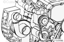
Most Signature™, ISX, and QSX15 engine models are equipped with wastegate turbochargers to limit the peak boost level and increase engine response at low rpm.
The wastegate actuator hose takes boost pressure from the intake manifold through the control valve to the wastegate capsule.
Exhaust and turbocharger components could be hot. Use caution and wear protective clothing when handling these components.
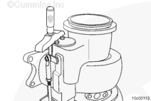
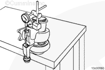
To verify the wastegate actuator travel, install Service Tool, Part Number 3165168, on the wastegate cover with the magnetic base and the dial indicator resting on the end of the actuator end link.
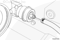
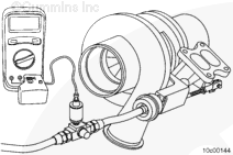
Disconnect the air supply line from the wastegate actuator and install the air line from the air control valve, Part Number ST-990-40, to the wastegate actuator.
Install the male quick-connect fitting, Part Number 3377244 (1), into the air control valve, Part Number ST-990-40 (2), to the wastegate actuator for use with the Compuchek™ quick-disconnect fitting, Part Number 3376859 (3) attached to the pressure transducer, Part Number 3164491 (4).
Measure the actuator rod for correct travel. If the actuator travel is not within the specifications, the wastegate must be adjusted. If adjustment is required, remove the turbocharger.
To make sure an accurate measurement is obtained, it is essential to use the specified tools and procedures.
Turbocharger Wastegate Rod Travel at 100 kPa [14.5 psi]
To obtain an accurate measurement, do not remove the wastegate valve cover or take the measurement from the top of the capscrew that secures the wastegate valve cover.
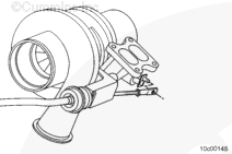
Use a micrometer depth gauge. To made a measurement from the face of the wastegate valve cover to the end of the wastegate actuator end link. Do not apply air pressure to the wastegate actuator.
If the wastegate wear measurement is less than 25.654 mm [1.010 in] then the turbocharger wastegate actuator can be recalibrated and the turbocharger returned to service. If the wastegate wear measurement is greater than 25.654 mm [1.010 in], replace the turbocharger turbine housing.
Wear appropriate eye and face protection when using compressed air. Flying debris and dirt can cause bodily injury.
CAUTION
Be careful not to bend the control lever.
Air Regulator with Pressure Gauge
Slowly apply regulated air pressure to the boost capsule. A maximum of 310 kPa [45 psi] can be used. Disconnect the boost capsule actuator rod end from the turbocharger wastegate lever rod when the rod is loose on the lever.
NOTE: If the boost capsule diaphragm material is ruptured and will not hold air pressure, it can be necessary to manually pull the control rod outward in order to overcome boost capsule spring-tension for removal of the control rod from the turbocharger wastegate lever pin while applying air pressure.
Disconnect the control rod from the turbocharger wastegate lever pin.
If there is a turnbuckle with an adjusting link, do NOT adjust the piston guided actuator by turning the rod of the actuator. This will damage the rubber diaphragm inside the actuator. The knurled turnbuckle on the new end adjusting link must be used.
Leave the setting pressure air supply connected to the wastegate capsule.
To reduce the possibility of breaking the wastegate pivot pin, use a wrench on the end link to support it while loosening and/or tightening the actuator end-link locknut.
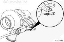
Remove the actuator end-link retaining clip.
Remove the actuator end link from the wastegate lever.
If there is a turnbuckle with an adjusting link, do NOT adjust the piston guided actuator by turning the rod of the actuator. This will damage the rubber diaphragm inside the actuator. The knurled turnbuckle on the new end adjusting link must be used.
Adjust the length of the end link by rotating to obtain nominal travel.
With the valve held closed (pushed toward the compressor housing), rotate the end link until the hole aligns with the crank-arm pin, so the end link can be fitted over the pin without using force.
The setting is correct if, by rotating the end link clockwise an extra half-turn, the end link can no longer be fitted onto the crank-arm pin.
Hello, I'm Jack, a diesel engine fan and a blogger. I write about how to fix and improve diesel engines, from cars to trucks to generators. I also review the newest models and innovations in the diesel market. If you are interested in learning more about diesel engines, check out my blog and leave your feedback.
View all posts by Jack


 CAUTION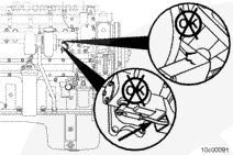
 WARNING










;)
;)
;)
;)
;)
;)
;)
;)
;)
;)
;)
;)
;)
;)
;)
;)
;)
;)
;)
;)
;)
;)
;)
;)
;)
;)
;)
;)
;)
;)
;)
;)
;)
;)
;)
;)
;)
;)
;)
;)
;)
;)
;)
;)
;)
;)
;)
;)
;)
;)
;)
;)
