NOTE: This repair requires the use of different turbocharger housing kits, depending on the engine CPL, and turbocharger serial number (found on the turbocharger dataplate). Reference the appropriate parts release information to determine which turbocharger housing kit to use.
NOTE: This repair requires the use of different turbocharger housing kits, depending on the engine CPL, and turbocharger serial number (found on the turbocharger dataplate). Reference the appropriate parts release information to determine which turbocharger housing kit to use.
Check for an “S” mark on the top right corner of the turbocharger data tag. This mark indicates that this repair procedure has already been completed on this turbocharger.
If there is an “S” mark present, do not proceed with this repair procedure; proceed with turbocharger replacement.
Cover the oil supply and drain ports in the bearing housing. Use clean care parts, Part Number 4919216 and 4919221.
Keep fingers and hands away from the actuator link to reduce the possibility of personal injury as a result of sudden movement when air is supplied.
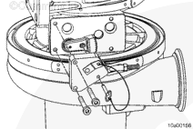
With the actuator in place, use coupling, Part Number 3824843, to connect a regulated air supply to the actuator air inlet. Check the actuator travel. Remove air to allow the actuator to retract. Mark or scribe the VG actuator rod at the base of the actuator. Measure the rod travel by measuring the distance from the base of the turbocharger actuator to the scribe mark. Use a straight edge steel ruler to measure.
The turbocharger actuator rod should extend more than 10 mm [0.394 in]. If it does not, verify the turbocharger actuator is functioning correctly. Refer to Procedure 010-113 in Section 10.If functioning correctly, install to the turbocharger and continue through the procedure.
Loosen the turbocharger turbine housing V-band clamp. The turbine housing V-band clamp locknut cover must be removed (use an 11 mm socket) before the locknut can be loosened.
After the clamp locknut is loosened, the V-band clamp can be spread and locked open by using the threaded end of the clamp, pressing it against the opposite end. This can aid in the removal of the turbine housing.
The turbine blades or the nozzle ring can be easily damaged. Care is required for the turbine housing removal process.
Slightly lift or angle the turbocharger while using a lead hammer to tap the turbine housing down against the bench surface.
Tap so that the turbine housing can be removed squarely. This will reduce the possibility of damage to the nozzle ring assembly. It can take a considerable amount of force to remove the turbine housing.
As the bearing housing and compressor housing assembly loosen, gently lift the assembly from the turbine housing and carefully place the compressor housing side down.
Check for excessive wear on the leading edge of the nozzle vanes.
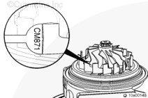
Use the nozzle vane wear gauge, Part Number 2892180, to check for excessive wear. Use the CM870 or CM871 end of the wear gauge, depending on the turbocharger. Place the nozzle vane wear gauge against each vane and down against the nozzle ring. It is important to place the gauge down completely against the nozzle ring face.
If the gauge can rock back and forth, the wear is not excessive. If the gauge can not rock back and forth, the nozzle vane has excessive wear.
If excessive wear is found and a vane does not pass the wear gauge check, the turbocharger must be replaced.
Use the shroud gauge tool, Part Number 2892179, to check the nozzle vanes for bending. It is important to use the correct shround gauge tool. ISX CM870 and ISX CM871 turbochargers use different shroud gauge tools. Check the part number to make sure the correct one is used.
Carefully align and rotate the shroud gauge tool until all nozzle vanes are engaged. Keep the shroud gauge tool parallel to the table. Slowly move it along the nozzle vanes until the shroud gauge tool is completely against the nozzle ring face.
The shroud gauge tool should be able to drop completely to the bottom of the nozzle ring assembly. Slowly pull the shroud plate tool back up and out of the nozzle vanes.
If the shroud gauge tool does not move freely, inspect for burrs that were missed on the nozzle vanes and remove, if possible.
If the shroud gauge tool continues to not fully engage, or if it requires excessive force to move up and down, bending of the nozzle vanes can possibly be required.
If it does not move freely after several attempts of bending a nozzle vane and checking with the shroud gauge tool, the turbocharger must be replaced.
Cover the oil supply and drain ports in the bearing housing. Use clean care parts, Part Number 4919216 and 4919221.
Check for an “S” mark on the top right corner of the turbocharger data tag. This mark indicates that this repair procedure has already been completed on this turbocharger.
If there is an “S” mark present, do not proceed with this repair procedure; proceed with turbocharger replacement.
Place the turbocharger on a flat sturdy table with the compressor housing down.
Lock the nozzle ring by using the sector gear positioning tool, Part Number 2892210.
Place the sector gear positioning tool over the sector gear and tighten the capscrews in the bottom left and top right VGT actuator mounting capscrew holes finger tight.
It is not necessary to place the locking pin in the sector gear positioning tool at this time.
It is important to have the sector gear positioning tool in place prior to removing the turbine housing in order to reduce the possibility of over-stroking the nozzle ring.
Loosen the turbocharger turbine housing V-band clamp. The turbine housing V-band clamp locknut cover must be removed (use an 11 mm socket) before the locknut can be loosened.
After the clamp locknut is loosened, the V-band clamp can be spread and locked open by using the threaded end of the clamp, pressing it against the opposite end. This can aid in the removal of the turbine housing.
The turbine blades or the nozzle ring can be easily damaged. Care is required for the turbine housing removal process.
Slightly lift or angle the turbocharger while using a lead hammer to tap the turbine housing down against the bench surface.
Tap so that the turbine housing can be removed squarely. This will reduce the possibility of damage to the nozzle ring assembly. It can take a considerable amount of force to remove the turbine housing.
As the bearing housing and compressor housing assembly loosen, gently lift the assembly from the turbine housing and carefully place the compressor housing side down.
With the turbine housing removed and the sector gear positioning tool, Part Number 2892210, still installed, move the sector gear back and forth by hand to check for smooth movement.
If the sector gear movement is not smooth, the turbocharger must be replaced.
Check for excessive wear on the leading edge of the nozzle vanes.
Use the nozzle vane wear gauge, Part Number 2892212, to check for excessive wear. Use the CM870 or CM871 end of the wear gauge, depending on the turbocharger. Place the nozzle vane wear gauge against each vane and down against the nozzle ring. It is important to place the gauge down completely against the nozzle ring face.
If the gauge can rock back and forth, the wear is not excessive. If the gauge can not rock back and forth, the nozzle vane has excessive wear.
If excessive wear is found and a vane does not pass the wear gauge check, the turbocharger must be replaced.
Use an abrasive disc, Part Number 3824541, and air tool or drill to clean up the burrs on the edge of each vane. Do not use excessive force or time to clean the vanes; burrs are fairly easy to remove.
Make sure the burrs are removed completely from each vane by feeling with the fingertip.
Carefully clean off any debris around the bearing housing surface and seal groove.
Use the sector gear positioning tool, Part Number 2892210, to lock the nozzle ring in the fully open position.
Place the sector gear positioning tool over the sector gear and tighten the capscrews in the bottom left and top right VGT actuator mounting capscrew holes hand-tight.
Insert the locking pin through the sector gear positioning tool and into the sector gear hole.
At this point, the nozzle ring should be at the fully extended position.
Use the shroud gauge tool, Part Number 2892180, to check the nozzle vanes for bending. It is important to use the correct shround gauge tool. ISX CM870 and ISX CM871 turbochargers use different shroud gauge tools. Check the part number to make sure the correct one is used.
Carefully align and rotate the shroud gauge tool until all nozzle vanes are engaged. Keep the shroud gauge tool parallel to the table. Slowly move it along the nozzle vanes until the shroud gauge tool is completely against the nozzle ring face.
The shroud gauge tool should be able to drop completely to the bottom of the nozzle ring assembly. Slowly pull the shroud plate tool back up and out of the nozzle vanes.
If the shroud gauge tool does not move freely, inspect for burrs that were missed on the nozzle vanes and remove, if possible.
If the shroud gauge tool continues to not fully engage, or if it requires excessive force to move up and down, bending of the nozzle vanes can possibly be required.
If it does not move freely after several attempts of bending a nozzle vane and checking with the shroud gauge tool, the turbocharger must be replaced.
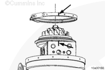
To install the turbine housing, position the V-band clamp over the bearing housing and align the ink marks applied during the disassembly process.
The V-band clamp can be spread and locked open by pressing the threaded end of the clamp against the opposite end. This will aid in allowing the turbine housing to drop into place.
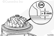
With the nozzle ring still at an extended position, carefully lower the turbine housing into the bearing and compressor housing assembly until the nozzle vanes contact the shround plate.
Carefully rotate the turbine housing, as needed, in order to engage all of the nozzle vanes.
Remain as parallel to the table as possible while lowering the turbine housing, until the nozzle vanes are fully engaged.
Keep fingers and hands away from the actuator link to reduce the possibility of personal injury as a result of sudden movement when air is supplied.
Use coupling, Part Number 3824843, to connect a regulated air supply to the actuator air inlet. Check the actuator travel. Remove air to allow the actuator to retract. Use a straight edge steel ruler to measure.
The turbocharger actuator rod should extend more than 10 mm [0.394 in].
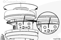
If movement is not smooth, or if there is not full travel, rotate the turbine housing counterclockwise. Then, rotate clockwise back to the alignment marks.
Check for full travel of the actuator rod.
Several rotational movements can need to be made in order to correctly align the nozzle ring and the sector gear.
To install the turbine housing, position the V-band clamp over the bearing housing and align the ink marks applied during the disassembly process.
The V-band clamp can be spread and locked open by pressing the threaded end of the clamp against the opposite end. This will aid in allowing the turbine housing to drop into place.
Make sure the sector gear positioning tool is still installed and the nozzle ring is at the fully extended position (the locking pin should be installed).
Carefully lower the turbine housing into the bearing and compressor housing assembly until the nozzle vanes contact the shroud plate.
Carefully rotate the turbine housing, as needed, in order to engage all of the nozzle vanes.
Remain as parallel to the table as possible while lowering the turbine housing, until the nozzle vanes are fully engaged.
Move the sector gear back and forth by hand to check for smooth movement.
If movement is not smooth, rotate the turbine housing counterclockwise. Then, rotate clockwise back to the alignment marks.
Check for smooth movement of the sector gear again. Several rotational movements can need to be made in order to correctly align the nozzle ring and the sector gear.
The sector gear travel gauges are designed for specific turbocharger models. To determine the correct gauge, verify the turbocharger model number from the turbocharger dataplate. Select the gauge that matches the first three letters of the turbocharger model number.
If the turbocharger data tag is missing or covered with paint, an alternate method of determining the turbocharger model number is to measure the distance between the top of the cup plug hole to the bearing housing edge.
If the distance is greater than 19 mm [0.748 in], the turbocharger model is HE4xx.
If the distance is less than 19 mm [0.748 in], the model is HE5xx.
Rotate the sector gear clockwise, toward the turbocharger compressor housing, until it stops. The edge of the sector gear must be in the green acceptance zone of the gauge.
If the sector gear does not go through the full range of motion, or if the sector gear requires excessive force to move it by hand, rotate the turbine housing back and forth until a smooth and full motion of the sector gear is achieved.
If a malfunction resulted in coolant, oil, excessive fuel, or excessive black smoke entering the exhaust system, the aftertreatment system must be inspected. Refer to Procedure 014-013 in Section 14.
Hello, I'm Jack, a diesel engine fan and a blogger. I write about how to fix and improve diesel engines, from cars to trucks to generators. I also review the newest models and innovations in the diesel market. If you are interested in learning more about diesel engines, check out my blog and leave your feedback.
View all posts by Jack


 WARNING


 CAUTION











;)
;)
;)
;)
;)
;)
;)
;)
;)
;)
;)
;)
;)
;)
;)
;)
;)
;)
;)
;)
;)
;)
;)
;)
;)
;)
;)
;)
;)
;)
;)
;)
;)
;)
;)
;)
;)
;)
;)
;)
;)
;)
;)
;)
;)
;)
;)
;)
;)
;)
;)
;)
;)
;)
;)
;)
;)
;)
;)
;)
;)
;)
;)
;)
;)
;)
;)
;)
;)
;)
;)
;)
;)
;)
;)
;)
;)
;)
;)
;)
;)
;)