|
Engine Coolant Temperature Sensor Circuit – Shorted High
|

Overview
| CODE | REASON | EFFECT |
| Fault Code: 144 PID: P110 SPN: 110 FMI: 3 LAMP: Amber SRT: |
Engine Coolant Temperature Sensor Circuit – Shorted High. High signal voltage detected at the engine coolant temperature sensor pin at the ECM. |
None on performance. No engine protection for coolant temperature. |
|
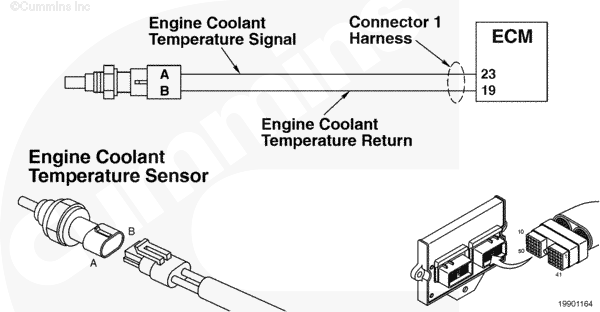
Engine Coolant Temperature Sensor Circuit |
 |
;)
;)
Circuit Description
The electronic control module (ECM) uses the coolant temperature sensor for engine protection purposes.
Component Location
The coolant temperature sensor is located on the left side of the block, behind the ECM.
Shop Talk
All temperature sensors:
- The resistance of the sensor varies with temperature. The reading you observe will compare to the following table if the sensor is functioning properly.
| Temperature (°C) | Temperature [°F] | Resistance (ohms) |
| 0 | 32 | 30k to 36k |
| 25 | 77 | 9k to 11k |
| 50 | 122 | 3k to 4k |
| 75 | 167 | 1350 to 1500 |
| 100 | 212 | 600 to 675 |
- This fault code can log in extremely cold weather.
Cautions and Warnings
 WARNING WARNING Do not remove the pressure cap from a hot engine. Wait until the coolant temperature is below 50°C [120°F] before removing the pressure cap. Heated coolant spray or steam can cause personal injury.
|
 CAUTION CAUTION To reduce the possibility of damaging a new ECM, all other active fault codes must be investigated prior to replacing the ECM. |
|
CAUTION To reduce the possibility of pin and harness damage, use the following test leads when taking a measurement: |
Troubleshooting Steps
| STEPS | SPECIFICATIONS | |
|---|---|---|
| STEP 1. | Check the fault codes. | |
| STEP 1A. Check for inactive fault codes. | Fault Code 144 inactive? | |
| STEP 2. | Check the coolant temperature sensor and circuit. | |
| STEP 2A. Inspect the coolant temperature sensor and connector pins. | Dirty or damaged pins? | |
| STEP 2B. Check the sensor resistance. | 175 ohms to 274k ohms? | |
| STEP 3. | Check the ECM and engine harness. | |
| STEP 3A. Inspect the ECM and engine harness connector pins. | Dirty or damaged pins? | |
| STEP 3B. Check for an open circuit in the engine harness. | Less than 10 ohms? | |
| STEP 3C. Check for an open circuit in the engine harness. | ||
| STEP 3C. Check for a pin to pin short circuit in the engine harness. | Greater than 100k ohms? | |
| STEP 3D. Check for an inactive fault code. | Fault Code 144 inactive? | |
| STEP 4. | Clear the fault codes. | |
| STEP 4A. Disable the fault code. | Fault Code 144 inactive? | |
| STEP 4B. Clear the inactive fault codes. | All fault codes cleared? | |
Guided Step 1 – Check the fault codes.
| Guided Step 1A – Check for inactive fault codes. | |
|---|---|
Conditions
Action
|
|
|
Fault Code 144 inactive? |
|
| YES | NO |
| No Repair | No Repair |
Guided Step 2 – Check the coolant temperature sensor and circuit.
| Guided Step 2A – Inspect the coolant temperature sensor and connector pins. | |
|---|---|
Conditions
Action
For general inspection techniques, refer to Component Connector and Pin Inspection, Procedure 019-361. |
|
|
Dirty or damaged pins? |
|
| YES | NO |
|
A defective connection has been detected in the sensor or harness connector. Repair the damaged pins. Repair or replace the engine harness, whichever has the damaged pins. |
No Repair |
| Guided Step 2B – Check the sensor resistance. | |
|---|---|
Conditions
Action
|
|
|
175 ohms to 274k ohms? |
|
| YES | NO |
| No Repair |
Replace the coolant temperature sensor. Refer to Procedure 019-019 |
Guided Step 3 – Check the ECM and engine harness.
| Guided Step 3A – Inspect the ECM and engine harness connector pins. | |
|---|---|
Conditions
Action
For general inspection techniques, refer to Component Connector and Pin Inspection, Procedure 019-361. |
|
|
Dirty or damaged pins? |
|
| YES | NO |
|
A defective connection has been detected in the ECM connector or engine harness connector. Repair the damaged pins. Repair or replace the engine harness, whichever has the damaged pins. |
No Repair |
| Guided Step 3B – Check for an open circuit in the engine harness. | |
|---|---|
Conditions
Action
Refer to circuit diagram or wiring diagram for connector pin identification. For general resistance measurement techniques, refer to the Resistance Measurements Using a Multimeter and Wiring Diagram, Procedure 019-360. |
|
|
Less than 10 ohms? |
|
| YES | NO |
| No Repair |
An open RETURN circuit has been detected in the engine harness. Repair the damaged pins. Repair or replace the engine harness, whichever has the damaged pins. |
| Guided Step 3B-1 – Check for an open circuit in the engine harness. | |
|---|---|
Conditions
Action
Refer to circuit diagram or wiring diagram for connector pin identification. For general resistance measurement techniques, refer to the Resistance Measurements Using a Multimeter and Wiring Diagram, Procedure 019-360. |
|
|
Less than 10 ohms? |
|
| YES | NO |
| No Repair |
An open SIGNAL circuit has been detected in the engine harness. Repair the damaged pins. Repair or replace the engine harness, whichever has the damaged pins. |
| Guided Step 3C – Check for a pin to pin short circuit in the engine harness. | |
|---|---|
Conditions
Action
Refer to circuit diagram or wiring diagram for connector pin identification. For general resistance measurement techniques, refer to the Resistance Measurements Using a Multimeter and Wiring Diagram, Procedure 019-360. |
|
|
Greater than 100k ohms? |
|
| YES | NO |
| No Repair |
An pin to pin short circuit on the SIGNAL pin has been detected in the engine harness. Repair the damaged pins. Repair or replace the engine harness, whichever has the damaged pins. |
| Guided Step 3D – Check for inactive fault codes. | |
|---|---|
Conditions
Action
|
|
|
Fault Code 144 inactive? |
|
| YES | NO |
| No Repair |
Replace the ECM. Call for pre-authorization. Refer to Procedure 019-031. |
Guided Step 4 – Clear the fault codes.
| Guided Step 4A – Disable the fault code. | |
|---|---|
Conditions
Action
|
|
|
Fault Code 144 inactive? |
|
| YES | NO |
| No Repair | No Repair |
| Guided Step 4B – Clear the inactive fault codes. | |
|---|---|
Conditions
Action
|
|
|
All fault codes cleared? |
|
| YES | NO |
| No Repair | No Repair |
|
Repair complete
|
Appropriate troubleshooting charts
|