|
Intake Manifold Temperature Sensor Circuit – Shorted Low
|

Overview
| CODE | REASON | EFFECT |
| Fault Code: 154 PID: P105 SPN: 105 FMI: 4 LAMP: Amber SRT: |
Intake Manifold Temperature Sensor Circuit – Shorted Low. |
Possible reduced performance. Fan will stay ON if controlled by ECM. No engine protection for intake manifold air temperature. |
|
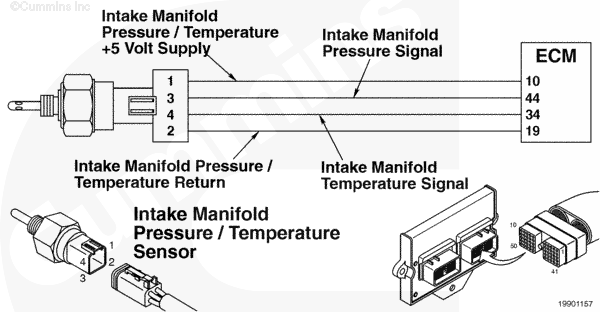
Intake Manifold Temperature Sensor Circuit |
 |
Circuit Description
The electronic control module (ECM) uses the intake manifold pressure/temperature sensor input to determine the temperature of the air mixture entering the engine.
Component Location
The intake manifold pressure/temperature sensor is located in the intake manifold housing (combination sensor with pressure).
Shop Talk
All temperature sensors:
- The resistance of the sensor varies with temperature. The reading you observe should compare to the following table if the sensor is functioning properly.
| Temperature (°C) | Temperature [°F] | Resistance (ohms) |
| 0 | 32 | 30k to 36k |
| 25 | 77 | 9k to 11k |
| 50 | 122 | 3k to 4k |
| 75 | 167 | 1350 to 1500 |
| 100 | 212 | 600 to 675 |
Cautions and Warnings
 CAUTION CAUTION To reduce the possibility of damaging a new ECM, all other active fault codes must be investigated prior to replacing the ECM. |
|
CAUTION To reduce the possibility of pin and harness damage, use the following test leads when taking a measurement: |
Troubleshooting Steps
| STEPS | SPECIFICATIONS | |
|---|---|---|
| STEP 1. | Check the fault codes. | |
| STEP 1A. Check for an inactive fault code. | Fault Code 154 active? | |
| STEP 2. | Check the intake manifold air temperature sensor and circuit. | |
| STEP 2A. Inspect the intake manifold air temperature sensor and connector pins. | Dirty or damaged pins? | |
| STEP 2B. Check the circuit response. | Fault Code 153 active and Fault Code 154 inactive? | |
| STEP 2C. Check the fault codes and verify sensor condition. | Fault Code 154 active? | |
| STEP 3. | Check the ECM and engine harness. | |
| STEP 3A. Inspect the ECM and engine harness connector pins. | Dirty or damaged pins? | |
| STEP 3B. Check for a pin to pin short circuit in the engine harness. | Greater than 100k ohms? | |
| STEP 3C. Check for a pin short circuit to ground. | Greater than 100k ohms? | |
| STEP 3D. Check for an inactive fault code. | Fault Code 154 inactive? | |
| STEP 4. | Clear the fault codes. | |
| STEP 4A. Disable the fault code. | Fault Code 154 inactive? | |
| STEP 4B. Clear the inactive fault codes. | All fault codes cleared? | |
Guided Step 1 – Check the fault codes.
| Guided Step 1A – Check for an inactive fault code. | |
|---|---|
Conditions
ActionUse INSITE™ electronic service tool to read the fault codes. |
|
|
Fault Code 154 inactive? |
|
| YES | NO |
| No Repair | No Repair |
Guided Step 2 – Check the intake manifold air temperature sensor and circuit.
| Guided Step 2A – Inspect the intake manifold air temperature sensor and connector pins. | |
|---|---|
Conditions
Action
For general inspection techniques refer to Component Connector and Pin Inspection, Procedure 019-361. |
|
|
Dirty or damaged pins? |
|
| YES | NO |
|
A defective connection has been detected in the sensor or harness connector. Repair the damaged pins. Repair or replace the engine harness, whichever has the damaged pins. |
No Repair |
| Guided Step 2B – Check the circuit response | |
|---|---|
Conditions
Action
|
|
|
Fault Code 153 active and Fault Code 154 inactive? |
|
| YES | NO |
| No Repair | No Repair |
| Guided Step 2C – Check the fault codes and verify sensor condition. | |
|---|---|
Conditions
ActionUse INSITE™ electronic service tool to read the fault codes. |
|
|
Fault Code 154 active? |
|
| YES | NO |
|
A defective sensor has been detected. Replace the intake manifold air temperature sensor. Refer to Procedure 019-354. |
No Repair |
Guided Step 3 – Check the ECM and engine harness.
| Guided Step 3A – Inspect the ECM and engine harness connector pins. | |
|---|---|
Conditions
Action
For general inspection techniques refer to Component Connector and Pin Inspection, Procedure 019-361. |
|
|
Dirty or damaged pins? |
|
| YES | NO |
|
A defective connection has been detected in the ECM connector or engine harness. Repair the damaged pins. Repair or replace the engine harness, whichever has the damaged pins. |
No Repair |
| Guided Step 3B – Check for a pin to pin short circuit in the engine harness. | |
|---|---|
Conditions
Action
Refer to the circuit diagram or wiring diagram for component pin identification. For general resistance measurement techniques refer to the Resistance Measurements Using a Multimeter and Wiring Diagram, Procedure 019-360. |
|
|
Greater than 100k ohms? |
|
| YES | NO |
| No Repair |
A pin to pin short circuit on the SIGNAL line has been detected in the engine harness. Repair or replace the engine harness, whichever has the damaged pins. |
| Guided Step 3C – Check for a pin short circuit to ground. | ||
|---|---|---|
Conditions
Action
|
|
|
|
Greater than 100k ohms? |
||
| YES | NO | |
| No Repair |
A pin to ground short circuit on the SIGNAL line has been detected in the engine harness. Repair or replace the engine harness, whichever has the damaged pins. |
|
;)
;)
;)
;)
| Guided Step 3D – Check for an inactive fault code. | |
|---|---|
Conditions
Action
|
|
|
Fault Code 154 inactive? |
|
| YES | NO |
| No Repair |
Replace the ECM. Call for pre-authorization. Refer to Procedure 019-031. |
Guided Step 4 – Clear the fault codes.
| Guided Step 4A – Disable the fault code. | |
|---|---|
Conditions
Action
|
|
|
Fault Code 154 inactive? |
|
| YES | NO |
| No Repair | No Repair |
| Guided Step 4B – Clear the inactive fault codes. | |
|---|---|
Conditions
Action
|
|
|
All fault codes cleared? |
|
| YES | NO |
| No Repair | No Repair |
|
Repair complete
|
Appropriate troubleshooting charts
|