|
Fuel Control Valve Circuit – Shorted Low
|

Overview
| CODE | REASON | EFFECT |
| Fault Code: 511 PID: S18 SPN: 633 FMI: 4 LAMP: Red SRT: |
Fuel Control Valve Circuit – Shorted Low. Low voltage detected at the ECM. |
Engine will die or not start. |
|
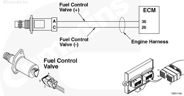
Fuel Control Valve Circuit |
 |
Circuit Description
The electronic control module (ECM) uses this valve to meter the fuel into the fuel housing.
Component Location
The fuel control valve is located in the fuel housing next to the gas mass flow sensor.
Shop Talk
This valve is normally closed when no power is applied. The valve is pulse-width modulated.
Cautions and Warnings
 CAUTION CAUTION To reduce the possibility of damaging a new ECM, all other active fault codes must be investigated prior to replacing the ECM. |
|
CAUTION To reduce the possibility of pin and harness damage, use the following test leads when taking a measurement: |
Troubleshooting Steps
| STEPS | SPECIFICATIONS | |
|---|---|---|
| STEP 1. | Check the fault codes. | |
| STEP 1A. Check for an inactive fault code. | Fault Code 511 inactive? | |
| STEP 2. | Check the fuel control valve and circuit. | |
| STEP 2A. Inspect the fuel control valve and connector pins. | Dirty or damaged pins? | |
| STEP 2B. Check for an open circuit in the fuel control valve. | 2 ohms to 5 ohms? | |
| STEP 2B-1. Check for a short to ground in the fuel control valve. | ||
| STEP 2C. Check the fuel control valve supply voltage, supply line and return circuit. | Greater than 5 VDC? | |
| STEP 3. | Check the ECM and engine harness. | |
| STEP 3A. Inspect the ECM and engine harness connector pins. | Dirty or damaged pins? | |
| STEP 3B. Check for a pin short circuit to ground. | Greater than 100k ohms? | |
| STEP 3C. Check for a pin to pin short circuit in the engine harness. | Greater than 100k ohms? | |
| STEP 3D. Check for an inactive fault code. | Fault Code 511 inactive? | |
| STEP 4. | Clear the fault codes. | |
| STEP 4A. Disable the fault code. | Fault Code 511 inactive? | |
| STEP 4B. Clear the inactive fault codes. | All fault codes cleared? | |
Guided Step 1 – Check the fault codes.
| Guided Step 1A – Check for an inactive fault code. | |
|---|---|
Conditions
Action
|
|
|
Fault Code 511 inactive? |
|
| YES | NO |
| No Repair | No Repair |
Guided Step 2 – Check the fuel control valve and circuit.
| Guided Step 2A – Inspect the fuel control valve and connector pins. | |
|---|---|
Conditions
Action
For general inspection techniques, refer to Component Connector and Pin Inspection, Procedure 019-361. |
|
|
Dirty or damaged pins? |
|
| YES | NO |
|
Repair the damaged pins. Repair or replace the harness, or replace the valve, whichever has the damaged pins.
|
No Repair |
| Guided Step 2B – Check for an open circuit in the fuel control valve. | |
|---|---|
Conditions
Action
Refer to the circuit diagram or wiring diagram for connector pin identification. For general resistance measurement techniques, refer to Resistance Measurements Using a Multimeter and Wiring Diagram, Procedure 019-360 |
|
|
2 ohms to 5 ohms? |
|
| YES | NO |
| No Repair |
Replace the fuel control valve. Refer to Procedure 019-102. |
| Guided Step 2B-1 – Check for a short to ground in the fuel control valve. | |
|---|---|
Conditions
Action
Refer to the circuit diagram or wiring diagram for connector pin identification. For general resistance measurement techniques, refer to Resistance Measurements Using a Multimeter and Wiring Diagram, Procedure 019-360 |
|
|
Greater than 100k ohms? |
|
| YES | NO |
| No Repair |
Replace the fuel control valve. Refer to Procedure 019-102. |
| Guided Step 2C – Check the fuel control valve supply voltage, supply line and return circuit. | |
|---|---|
Conditions
Action
|
|
|
Greater than 5 VDC? |
|
| YES | NO |
| No Repair | No Repair |
Guided Step 3 – Check the ECM and engine harness.
| Guided Step 3A – Inspect the ECM and engine harness connector pins. | |
|---|---|
Conditions
Action
For general inspection techniques, refer to Component Connector and Pin Inspection, Procedure 019-361. |
|
|
Dirty or damaged pins? |
|
| YES | NO |
|
A defective connection has been detected in the ECM connector 1 or the engine harness connector. Repair the damaged pins. Repair or replace the harness, whichever has the damaged pins. |
No Repair |
| Guided Step 3B – Check for a pin short to ground. | |
|---|---|
Conditions
Action
Refer to the circuit diagram or wiring diagram for connector pin identification. For general resistance measurement techniques, refer to Resistance Measurements Using a Multimeter and Wiring Diagram, Procedure 019-360 |
|
|
Greater than 100k ohms? |
|
| YES | NO |
| No Repair |
A pin to ground short circuit on the fuel control valve output line has been detected in the engine harness. Repair the damaged pins. Repair or replace the harness, whichever has the damaged pins. |
| Guided Step 3C – Check for a pin to pin short circuit in the engine harness. | |
|---|---|
Conditions
Action
|
|
|
Greater than 100k ohms? |
|
| YES | NO |
| No Repair |
A pin to pin short circuit on the fuel control valve supply line has been detected in the engine harness. Repair the damaged pins. Repair or replace the harness, whichever has the damaged pins. |
| Guided Step 3D – Check for an inactive fault code. | |
|---|---|
Conditions
Action
|
|
|
Fault Code 511 inactive? |
|
| YES | NO |
| No Repair |
Replace the ECM. Call for pre-authorization. Refer to Procedure 019-031. |
Guided Step 4 – Clear the fault codes.
| Guided Step 4A – Disable the fault code. | |
|---|---|
Conditions
Action
|
|
|
Fault Code 511 inactive? |
|
| YES | NO |
| No Repair | No Repair |
| Guided Step 4B – Clear the inactive fault codes. | |
|---|---|
Conditions
Action
|
|
|
All fault codes cleared? |
|
| YES | NO |
| No Repair | No Repair |
|
Repair complete
|
Appropriate troubleshooting charts
|

;)
;)