|
Fuel Pressure Sensor Circuit, Secondary- Shorted Low
|

Overview
| CODE | REASON | EFFECT |
| Fault Code: 547 PID: P94 SPN: 94 FMI: 4 LAMP: Amber SRT: |
Fuel Pressure Sensor Circuit, Secondary- Shorted Low. Low voltage (short to ground) detected at the ECM. |
Possible effect on performance. |
|
Fuel Pressure/Temperature Sensor Circuit |
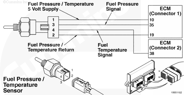 |
Circuit Description
The electronic control module (ECM) uses the fuel pressure/temperature sensor to measure the secondary fuel pressure to the engine. This is a combination sensor with the temperature sensor.
Component Location
The fuel pressure/temperature sensor, secondary, is located in the fuel housing.
Shop Talk
The fuel pressure/temperature sensor measures the secondary fuel pressure to the engine. This is after the low pressure regulator. The fuel pressure/temperature sensor, secondary, is an absolute sensor.
Cautions and Warnings
 CAUTION CAUTION To reduce the possibility of damaging a new ECM, all other active fault codes must be investigated prior to replacing the ECM. |
|
CAUTION To reduce the possibility of pin and harness damage, use the following test leads when taking a measurement: |
Troubleshooting Steps
| STEPS | SPECIFICATIONS | |
|---|---|---|
| STEP 1. | Check the fault codes. | |
| STEP 1A. Check for fault codes. | Fault Code 352 active? | |
| STEP 1B. Check for an inactive fault code. | Fault Code 547 inactive? | |
| STEP 2. | Check the fuel pressure sensor and circuit. | |
| STEP 2A. Inspect the fuel pressure sensor and connector pins. | Dirty or damaged pins? | |
| STEP 2B. Check the sensor supply voltage and return circuit. | 4.5 to 5.25 VDC? | |
| STEP 2C. Check the circuit response. | Fault Code 546 active and Fault Code 547 inactive? | |
| STEP 2D. Check the fault codes and verify sensor condition. | Fault Code 547 inactive? | |
| STEP 3. | Check the ECM and engine harness. | |
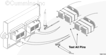
| STEP 3A. Inspect the ECM and engine harness connector pins. | Dirty or damaged pins? | |
| STEP 3B. Check for an open circuit in the engine harness. | Less than 10 ohms? | |
| STEP 3C. Check for an open circuit in the engine harness. | Less than 10 ohms? | |
| STEP 3D. Check for a pin to pin short circuit in the engine harness. | Greater than 100k ohms? | |
| STEP 3E. Check for a pin short circuit to ground. | Greater than 100k ohms? | |
| STEP 3F. Check for an inactive fault code. | Fault Code 547 inactive? | |
| STEP 4. | Clear the fault codes. | |
| STEP 4A. Disable the fault code. | Fault Code 547 inactive? | |
| STEP 4B. Clear the inactive fault codes. | All fault codes cleared? | |
Guided Step 1 – Check the fault codes.
| Guided Step 1A – Check for fault codes. | |
|---|---|
Conditions
Action
|
|
|
Fault Code 352 active? |
|
| YES | NO |
| No Repair | No Repair |
|
Fault Code 352
|
|
| Guided Step 1B – Check for an inactive fault code. | |
|---|---|
Conditions
Action
|
|
|
Fault Code 547 inactive? |
|
| YES | NO |
| No Repair | No Repair |
Guided Step 2 – Check the fuel pressure sensor and connector pins.
| Guided Step 2A – Inspect the fuel pressure sensor and connector pins. | |
|---|---|
Conditions
Action
For general inspection techniques refer to Component Connector and Pin Inspection, Procedure 019-361. |
|
|
Dirty or damaged pins? |
|
| YES | NO |
|
A defective connection has been detected in the sensor or harness connector. Repair the damaged pins. Repair or replace the engine harness, replace the sensor, whichever has the damaged pins.
|
No Repair |
| Guided Step 2B – Check the sensor supply voltage and return circuit. | |
|---|---|
Conditions
Action
Refer to the circuit diagram or wiring diagram for connector pin identification. |
|
|
4.5 to 5.25 VDC? |
|
| YES | NO |
| No Repair | No Repair |
| Guided Step 2C – Check the circuit response. | |
|---|---|
Conditions
Action
|
|
|
Fault Code 546 active and Fault Code 547 inactive? |
|
| YES | NO |
| No Repair | No Repair |
| Guided Step 2D – Check the fault codes and verify sensor condition. | |
|---|---|
Conditions
Action
|
|
|
Fault Code 547 active? |
|
| YES | NO |
|
A defective sensor has been detected. Replace the fuel pressure sensor. Refer to Procedure 019-153. |
No Repair |
Guided Step 3 – Check the ECM and engine harness.
| Guided Step 3A – Inspect the ECM and engine harness connector pins. | |
|---|---|
Conditions
Action
For general inspection techniques refer to Component Connector and Pin Inspection, Procedure 019-361. |
|
|
Dirty or damaged pins? |
|
| YES | NO |
|
A defective connection has been detected in the ECM or engine harness connectors. Repair the damaged pins. Repair or replace the engine harness, whichever has the damaged pins. |
No Repair |
| Guided Step 3B – Check for an open circuit in the engine harness. | |
|---|---|
Conditions
Action
Refer to the circuit diagram or wiring diagram for connector pin identification. For general resistance measurements techniques refer to the Resistance Measurements Using a Multimeter and Wiring Diagram, Procedure 019-360. |
|
|
Less than 10 ohms? |
|
| YES | NO |
| No Repair |
An open return circuit has been detected in the engine harness. Repair or replace the engine harness. |
| Guided Step 3C – Check for an open circuit in the engine harness. | |
|---|---|
Conditions
Action
Refer to the circuit diagram or wiring diagram for connector pin identification. For general resistance measurements techniques refer to the Resistance Measurements Using a Multimeter and Wiring Diagram, Procedure 019-360. |
|
|
Less than 10 ohms? |
|
| YES | NO |
| No Repair |
An open return circuit has been detected in the engine harness. Repair or replace the engine harness. |
| Guided Step 3D – Check for a pin to pin short circuit in the engine harness. | ||
|---|---|---|
Conditions
Action
Refer to the circuit diagram or wiring diagram for connector pin identification. For general resistance measurements techniques refer to the Resistance Measurements Using a Multimeter and Wiring Diagram, Procedure 019-360. |
|
|
|
Greater than 100k ohms? |
||
| YES | NO | |
| No Repair |
An pin to pin short circuit on the SIGNAL line has been detected in the engine harness. Repair or replace the engine harness. |
|
;)
;)
;)
;)
| Guided Step 3E – Check for a pin short circuit to ground. | |
|---|---|
Conditions
Action
Refer to the circuit diagram or wiring diagram for connector pin identification. For general resistance measurements techniques refer to the Resistance Measurements Using a Multimeter and Wiring Diagram, Procedure 019-360. |
|
|
Greater than 100k ohms? |
|
| YES | NO |
| No Repair |
An pin to ground short circuit on the SIGNAL line has been detected in the engine harness. Repair or replace the engine harness. |
| Guided Step 3F – Check for an inactive fault code. | |
|---|---|
Conditions
Action
|
|
|
Fault Code 547 inactive? |
|
| YES | NO |
| No Repair |
Replace the ECM. Call for pre-authorization. Replace the ECM. Refer to Procedure 019-031. |
Guided Step 4 – Clear the fault codes.
| Guided Step 4A – Disable the fault code. | |
|---|---|
Conditions
Action
|
|
|
Fault Code 547 inactive? |
|
| YES | NO |
| No Repair | No Repair |
| Guided Step 4B – Clear the inactive fault codes. | |
|---|---|
Conditions
Action
|
|
|
All fault codes cleared? |
|
| YES | NO |
| No Repair | No Repair |
|
Repair complete
|
Appropriate troubleshooting charts
|