Overview
Fault Code: 551
PID: P91
SPN: 91
FMI: 4
LAMP: Amber
SRT:
|
Accelerator Pedal or Lever Idle Validation Circuit – Voltage Below Normal, or shorted to a low source. No voltage detected simultaneously on both the idle validation off-idle and on-idle circuits.
|
Engine will only idle.
|
|
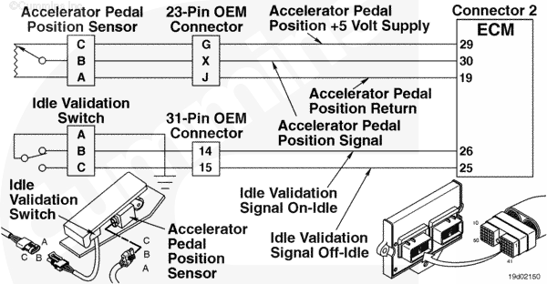
Idle Validation Switch Circuit |
|
|
Circuit Description
The electronic control module (ECM) uses this signal to determine the position of the accelerator pedal.
Component Location
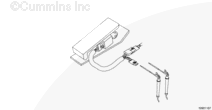
The idle validation switches are located in the accelerator pedal.
Shop Talk
The idle validation switch does not require twisted pair wiring.
Cautions and Warnings
 CAUTION
To reduce the possibility of damaging a new ECM, all other active fault codes must be investigated prior to replacing the ECM.
|
CAUTION
To reduce the possibility of pin and harness damage, use the following test leads when taking a measurement:
Part Number 3822758 – male Deutsch/AMP/Metri-Pack test lead
Part Number 3823995 – male Weather-Pack test lead.
|
Troubleshooting Steps
| STEPS |
SPECIFICATIONS |
| STEP 1. |
Check the fault codes. |
|
| |
STEP 1A. Read the fault codes. |
Fault Code 551 active? |
| STEP 2. |
Check the idle validation switch. |
|
| |
STEP 2A. Inspect the idle validation switch and OEM harness connector pins. |
Dirty or damaged pins? |
| |
STEP 2B. Read the fault codes. |
Fault Code 551 active? |
| |
STEP 2C. Check the resistance of the idle validation switch. |
On-idle resistance less than 125 ohms and Off-idle switch is more than 100k ohms? |
| STEP 3. |
Check the engine harness. |
|
| |
STEP 3A. Inspect the engine harness and ECM connector pins. |
Dirty or damaged pins? |
| |
STEP 3B. Check for a short circuit to ground. |
Both measurements greater than 100k ohms? |
| |
STEP 3B-1. Check for a short circuit to ground. |
|
| |
STEP 3C. Check for a short circuit from pin to pin. |
Greater than 100k ohms? |
| |
STEP 3C-1. Check for a short circuit from pin to pin. |
|
| |
STEP 3D. Check for an inactive fault code. |
Fault Code 551 inactive? |
| STEP 4. |
Clear the fault codes. |
|
| |
STEP 4A. Disable the fault code. |
Fault Code 551 inactive? |
| |
STEP 4B. Clear the inactive fault codes. |
All fault codes cleared? |
Guided Step 1 – Check the fault codes.
| Guided Step 1A – Read the fault codes. |
Conditions
- Turn keyswitch ON
- Connect the INSITE™ electronic service tool.
Action
Use INSITE™ electronic service tool to read the fault codes.
|
|
Fault Code 551 active?
|
| YES |
NO |
| No Repair |
No Repair |
|
|
|
Guided Step 2 – Check the idle validation switch.
| Guided Step 2A – Inspect the idle validation switch and OEM harness connector pins. |
Conditions
- Turn keyswitch OFF
- Disconnect the OEM harness from the idle validation switch.
Action
- Corroded pins
- Bent or broken pins
- Pushed back or expanded pins
- Wire insulation damage
- Moisture in or on the connector
- Missing or damaged connector seals
- Connector shell broken
- Dirt or debris in or on the connector pins.
For general inspection techniques, refer to Component Connector and Pin Inspection, Procedure 019-361.
|
|
Dirty or damaged pins?
|
| YES |
NO |
|
Repair the damaged pins. Repair or replace the harness, or replace the switch, whichever has the damaged pins.
- Flush the dirt, debris, or moisture from the connector pins using electronic contact cleaner, Part Number 3824510.
- Install the appropriate connector seal if it is damaged or missing.
- Repair the harness. Refer to Procedure 019-204.
- Replace the harness. Refer to Procedure 019-043.
- Replace the idle validation switch. Refer to Procedure 019-054.
|
No Repair |
|
|
|
| Guided Step 2B – Read the fault codes. |
Conditions
- Connect all components
- Turn keyswitch ON
- Connect INSITE™ electronic service tool.
Action
- Use INSITE™ electronic service tool to read the fault codes.
- Depress and release the accelerator pedal three times.
|
|
Fault Code 551 active?
|
| YES |
NO |
| No Repair |
No Repair |
|
|
|
| Guided Step 2C – Check the resistance of the idle validation switch. |
Conditions
- Turn keyswitch OFF
- Disconnect the OEM harness from the idle validation switch
- Make certain accelerator pedal is in the released position before measuring resistance.
Action
- Measure the resistance between the idle validation SIGNAL on-idle pin to the RETURN pin in the idle validation OEM harness sensor connector.
- Measure the resistance from the idle validation off-idle pin to the RETURN pin in the idle validation OEM harness sensor connector.
Refer to the circuit diagram or wiring diagram for connector pin identification.
For general resistance measurement techniques, refer to Resistance Measurements Using a Multimeter and Wiring Diagram, Procedure 019-360
|
|
|
On-idle resistance less than 125 ohms and Off-idle switch is more than 100k ohms?
|
| YES |
NO |
| No Repair |
Replace the idle validation switch. Refer to Procedure 019-054.
|
|
|
|
Guided Step 3 – Check the engine harness.
| Guided Step 3A – Inspect the engine harness and ECM connector pins. |
Conditions
- Turn keyswitch OFF
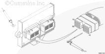
- Disconnect engine harness connector 1 and connector 2 from the ECM.
Action
- Corroded pins
- Bent or broken pins
- Pushed back or expanded pins
- Wire insulation damage
- Moisture in or on the connector
- Missing or damaged connector seals
- Connector shell broken
- Dirt or debris in or on the connector pins.
For general inspection techniques, refer to Component Connector and Pin Inspection, Procedure 019-361.
|
|
Dirty or damaged pins?
|
| YES |
NO |
|
Repair the damaged pins. Repair or replace the harness, or replace the ECM, whichever has the damaged pins.
- Flush the dirt, debris, or moisture from the connector pins using electronic contact cleaner, Part Number 3824510.
- Install the appropriate connector seal if it is damaged or missing.
- Repair the harness. Refer to Procedure 019-204.
- Replace the harness. Refer to Procedure 019-043.
- Replace the ECM. Call for pre-authorization.
- Refer to Procedure 019-031.
|
No Repair |
|
|
|
| Guided Step 3B – Check for a short circuit to ground. |
Conditions
- Turn keyswitch OFF
- Disconnect engine harness connector 2 from the ECM
- Disconnect the accelerator pedal from the OEM harness.
Action
- Measure the resistance between the idle validation SIGNAL on-idle pin in the engine harness ECM connector to engine block ground.
- Measure the resistance between the idle validation SIGNAL off-idle pin in the engine harness ECM connector to engine block ground.
|
|
|
Both measure greater than 100k ohms?
|
| YES |
NO |
| No Repair |
No Repair |
|
|
|
| Guided Step 3B-1 – Check for a short circuit to ground. |
Conditions
- Turn keyswitch OFF
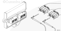
- Disconnect the OEM harness from the engine harness at the 31 pin OEM connector.
- Disconnect engine harness connector 2 from the ECM.
Action
- Measure the resistance between the idle validation SIGNAL on-idle pin in the engine harness ECM connector to engine block ground.
- Measure the resistance between the idle validation SIGNAL off-idle pin in the engine harness ECM connector to engine block ground.
|
|
|
Greater than 100k ohms?
|
| YES |
NO |
|
Repair or replace the OEM harnesses. Refer to the OEM service manual.
|
Repair the damaged pins. Repair or replace the harness, whichever has the damaged pins.
- Flush the dirt, debris, or moisture from the connector pins using electronic contact cleaner, Part Number 3824510.
- Install the appropriate connector seal if it is damaged or missing.
- Repair the harness. Refer to Procedure 019-204.
- Replace the harness. Refer to Procedure 019-043.
|
|
|
|
| Guided Step 3C – Check for a short circuit from pin to pin. |
Conditions
- Turn keyswitch OFF
- Disconnect engine harness connector 1 and connector 2 from the ECM
- Disconnect the accelerator pedal from the OEM harness.
Action
- Measure the resistance between the idle validation SIGNAL on-idle pin in engine harness ECM connector 2 to all other pins in the connector.
- Measure the resistance between the idle validation SIGNAL off-idle pin in engine harness ECM connector 2 to all other pins in the connector.
- Measure the resistance between the idle validation SIGNAL on-idle pin in engine harness ECM connector 2 to all pins in engine harness ECM connector 1.
- Measure the resistance between the idle validation SIGNAL off-idle pin in engine harness ECM connector 2 to all pins in engine harness ECM connector 1.
|
|
|
Greater than 100k ohms?
|
| YES |
NO |
| No Repair |
No Repair |
|
|
|
| Guided Step 3C-1 – Check for a short circuit from pin to pin. |
Conditions
- Turn keyswitch OFF
- Disconnect the OEM harness from the engine harness at the 23 pin and 31 pin OEM connectors.
- Disconnect engine harness connector 1 and connector 2 from the ECM.
Action
- Measure the resistance between the idle validation SIGNAL on-idle pin in engine harness ECM connector 2 to all other pins in the connector.
- Measure the resistance between the idle validation SIGNAL off-idle pin in engine harness ECM connector 2 to all other pins in the connector.
- Measure the resistance between the idle validation SIGNAL on-idle pin in engine harness ECM connector 2 to all pins in engine harness ECM connector 1.
- Measure the resistance between the idle validation SIGNAL off-idle pin in engine harness ECM connector 2 to all pins in engine harness ECM connector 1.
|
|
|
Greater than 100k ohms?
|
| YES |
NO |
|
Repair or replace the OEM harnesses. Refer to the OEM service manual.
|
Repair the damaged pins. Repair or replace the harness, whichever has the damaged pins.
- Flush the dirt, debris, or moisture from the connector pins using electronic contact cleaner, Part Number 3824510.
- Install the appropriate connector seal if it is damaged or missing.
- Repair the harness. Refer to Procedure 019-204.
- Replace the harness. Refer to Procedure 019-043.
|
|
|
|
| Guided Step 3D – Check for an inactive fault codes. |
Conditions
- Connect all components
- Turn keyswitch ON
- Connect INSITE™ electronic service tool.
Action
- Use INSITE™ electronic service tool to read the fault codes.
|
|
Fault Code 551 inactive?
|
| YES |
NO |
| No Repair |
Replace the ECM. Call for pre-authorization.
Refer to Procedure 019-031.
|
|
|
|
Guided Step 4 – Clear the fault codes.
| Guided Step 4A – Disable the fault code. |
Conditions
- Connect all components
- Turn keyswitch ON
- Connect INSITE™ electronic service tool.
Action
- Turn keyswitch ON
- Depress and release the accelerator pedal three times
- Use INSITE™ electronic service tool to verify that Fault Code 551 is inactive.
|
|
Fault Code 551 inactive?
|
| YES |
NO |
| No Repair |
Troubleshooting procedures need to be repeated from the beginning.
|
|
|
|
| Guided Step 4B – Clear the inactive fault codes. |
Conditions
- Connect all components
- Turn keyswitch ON
- Connect INSITE™ electronic service tool.
Action
- Use INSITE™ electronic service tool to erase the inactive fault codes.
|
|
All fault codes cleared?
|
| YES |
NO |
| No Repair |
Troubleshoot any remaining active fault codes.
|
|
Repair complete
|
Appropriate troubleshooting charts
|
Last Modified: 28-Sep-2004

;)
;)
;)
;)
;)
;)
;)
;)