|
Exhaust Back Pressure Sensor Circuit – Shorted Low
|

Overview
| CODE | REASON | EFFECT |
| Fault Code: 592 PID: S034 SPN: 648 FMI: 4 LAMP: Amber SRT: |
Exhaust Back Pressure Sensor Circuit – Shorted Low. Low voltage (short to ground) detected at the ECM connector. |
Possible reduced performance. |
|
Exhaust Back Pressure Sensor Circuit |
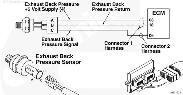 |
Circuit Description
The electronic control module (ECM) uses this sensor’s input to determine the pressure of the exhaust gas, which affects the fueling of the engine.
Component Location
The exhaust back pressure sensor is located above the rocker housing and is connected to the closed-crankcase ventilation filter bracket. The sensor utilizes a tube that is fitted into the exhaust outlet connection.
Refer to Procedure 100-002 (Engine Diagrams) in Section E for a detailed component location view.
Shop Talk
The exhaust back pressure sensor tube is vulnerable to the collection of condensation and sludge. Periodic maintenance of this tube should be performed. This sensor is located such that it is protected from extreme heat. Do
not relocate this sensor from its on-engine position.
On the L Gas Plus an OEM tube from the exhaust connects to an accumulator on the exhaust side of the engine. A tube then connects the accumulator to the exhaust back pressure sensor.
Cautions and Warnings
 CAUTION CAUTION To reduce the possibility of damaging a new ECM, all other active fault codes must be investigated prior to replacing the ECM. |
|
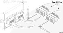
CAUTION To reduce the possibility of pin and harness damage, use the following test leads when taking a measurement: |
Troubleshooting Steps
| STEPS | SPECIFICATIONS | |
|---|---|---|
| STEP 1. | Check the fault codes. | |
| STEP 1A. Read the fault codes. | Fault Code 2186 active? | |
| STEP 1B. Check for an inactive fault code. | Fault Code 592 inactive? | |
| STEP 2. | Check the exhaust back pressure sensor and circuit. | |
| STEP 2A. Inspect the exhaust back pressure sensor and connector pins. | Dirty or damaged pins? | |
| STEP 2B. Check the sensor supply voltage and return circuit. | 4.5 to 5.25-VDC? | |
| STEP 2C. Check the circuit response. | Fault Code 592 active and Fault Code 591 inactive? | |
| STEP 2D. Check the fault codes and verify sensor condition. | Fault Code 591 active? | |
| STEP 3. | Check the ECM and engine harness. | |
| STEP 3A. Inspect the ECM and engine harness connector pins. | Dirty or damaged pins? | |
| STEP 3B. Check for an open circuit in the engine harness. | Less than 10 ohms? | |
| STEP 3C. Check for an open circuit in the engine harness. | Less than 10 ohms? | |
| STEP 3D. Check for a pin-to-pin short circuit from in the engine harness. | Greater than 100k ohms? | |
| STEP 3E. Check for a pin short circuit to ground. | Greater than 100k ohms? | |
| STEP 3F. Check for an inactive fault code. | Fault Code 592 inactive? | |
| STEP 4. | Clear the fault codes. | |
| STEP 4A. Disable the fault code. | Fault Code 592 inactive? | |
| STEP 4B. Clear the inactive fault codes. | All fault codes cleared? | |
Guided Step 1 – Check the fault codes.
| Guided Step 1A – Check for Fault Code 2186. | |
|---|---|
Conditions
ActionCheck for sensor supply fault codes. Use INSITE™ electronic service tool to read the fault codes. |
|
|
Fault Code 2186 active? |
|
| YES | NO |
| No Repair | No Repair |
|
Fault Code 2186
|
|
| Guided Step 1B – Check for an inactive fault code. | |
|---|---|
Conditions
ActionCheck for an inactive fault code. Use INSITE™ electronic service tool to read the fault codes. |
|
|
Fault Code 592 inactive? |
|
| YES | NO |
| No Repair | No Repair |
Guided Step 2 – Check the exhaust back pressure sensor and circuit.
| Guided Step 2A – Inspect the exhaust back pressure sensor and connector pins. | |
|---|---|
Conditions
ActionInspect the engine harness and exhaust back pressure sensor connector pins for the following:
|
|
|
Dirty or damaged pins? |
|
| YES | NO |
|
A damaged connection has been detected in the sensor or harness connector. Repair the damaged pins. Repair or replace the engine harness or replace the sensor, whichever has the damaged pins.
|
No Repair |
| Guided Step 2B – Check the sensor supply voltage and return circuit. | |
|---|---|
Conditions
ActionCheck the supply voltage and return circuit.
Refer to the circuit diagram or wiring diagram for connector pin identification. |
|
|
4.5 to 5.25-VDC? |
|
| YES | NO |
| No Repair | No Repair |
| Guided Step 2C – Check the circuit response. | |
|---|---|
Conditions
ActionPlace a jumper wire between the exhaust back pressure SUPPLY pin and the exhaust back pressure SIGNAL pin at the exhaust back pressure sensor connector of the engine harness.
|
|
|
Fault Code 591 active and Fault Code 592 inactive? |
|
| YES | NO |
| No Repair | No Repair |
| Guided Step 2D – Check the fault codes and verify sensor condition. | |
|---|---|
Conditions
ActionCheck for the appropriate circuit response after 30 seconds.
|
|
|
Fault Code 592 active? |
|
| YES | NO |
|
A damaged sensor has been detected. Replace the exhaust back pressure sensor. |
No Repair |
Guided Step 3 – Check the ECM and engine harness.
| Guided Step 3A – Inspect ECM and engine harness connector pins. | |
|---|---|
Conditions
ActionInspect the engine harness and ECM connector pins for the following:
|
|
|
Dirty or damaged pins? |
|
| YES | NO |
|
A damaged connection has been detected in the ECM connector or engine harness connector. Repair the damaged pins. Repair or replace the engine harness, or replace the ECM, whichever has the damaged pins.
|
No Repair |
| Guided Step 3B – Check for an open circuit in the engine harness. | |
|---|---|
Conditions
ActionCheck for an open circuit.
Refer to the circuit diagram or wiring diagram for connector pin identification. |
|
|
Less than 10 ohms? |
|
| YES | NO |
| No Repair |
An open SUPPLY circuit has been detected in the engine harness. Repair the damaged pins. Repair or replace the engine harness.
|
| Guided Step 3C – Check for an open circuit in the engine harness. | |
|---|---|
Conditions
ActionCheck for an open circuit.
Refer to the circuit diagram or wiring diagram for connector pin identification. |
|
|
Less than 10 ohms? |
|
| YES | NO |
| No Repair |
An open SIGNAL circuit has been detected in the engine harness. Repair the damaged pins. Repair or replace the engine harness.
|
| Guided Step 3D – Check for a pin-to-pin short circuit in the engine harness. | ||
|---|---|---|
Conditions
ActionCheck for a pin-to-pin short.
Refer to the circuit diagram or wiring diagram for connector pin identification. |
|
|
|
Greater than 100k ohms? |
||
| YES | NO | |
| No Repair |
A pin-to-pin short circuit on the SIGNAL line has been detected in the engine harness. Repair the damaged pins. Repair or replace the engine harness.
|
|
;)
;)
;)
;)
| Guided Step 3E – Check for a pin short circuit to ground. | |
|---|---|
Conditions
ActionCheck for a pin to ground short.
Refer to the circuit diagram or wiring diagram for connector pin identification. |
|
|
Greater than 100k ohms? |
|
| YES | NO |
| No Repair |
A pin to ground short circuit on the SIGNAL line has been detected in the engine harness. Repair the damaged pins. Repair or replace the engine harness.
|
| Guided Step 3F – Check for an inactive fault code. | |
|---|---|
Conditions
ActionCheck for the appropriate circuit response after 30 seconds. Use INSITE™ electronic service tool to read the fault codes. |
|
|
Fault Code 592 inactive? |
|
| YES | NO |
| No Repair |
|
Guided Step 4 – Clear the fault codes.
| Guided Step 4A – Disable the fault code. | |
|---|---|
Conditions
ActionDisable the fault code.
|
|
|
Fault Code 592 inactive? |
|
| YES | NO |
| No Repair |
Return to the troubleshooting steps or contact a Cummins® Authorized Repair Location if all steps have been completed and checked again. |
| Guided Step 4B – Clear the inactive fault codes. | |
|---|---|
Conditions
ActionClear the inactive fault codes.
|
|
|
All fault codes cleared? |
|
| YES | NO |
| No Repair |
Troubleshoot any remaining active fault codes. |
|
Repair complete
|
Appropriate troubleshooting charts
|