Batteries can emit explosive gases. To reduce the possibility of personal injury, always ventilate the compartment before servicing the batteries. To reduce the possibility of arcing, remove the negative (-) battery cable first and attach the negative (-) battery cable last.
NOTE: In order to remove the valve springs with the cylinder head installed, the piston of the cylinder being worked on must be brought to top dead center (TDC) to support the valves.
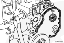
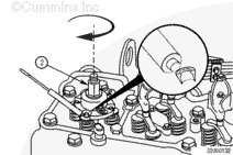
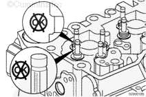
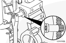
Use a barring tool, Part Number 3824591, to rotate the crankshaft to align the (TDC) marks on the gear cover and fuel pump gear.
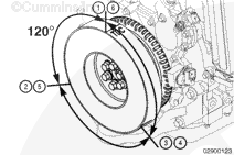
With the (TDC) marks for the number 1 cylinder aligned, mark the vibration damper for the location of (TDC) for the other cylinders.
Mark the vibration damper every 120 degrees with a marker directly on the damper or to a piece of masking tape applied to the outside diameter of the damper.
Service Tip: A protractor, camshaft degree wheel or angle/level indicator, Part Number 3375855, can be used to locate 120 degree increments around the vibration damper.
Mark the damper with the TDC indicator for each cylinder as shown. Two cylinders correspond to each 120 degree line.
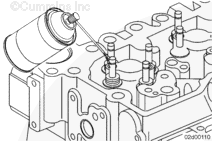
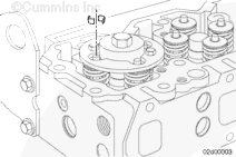
Compress the valve springs using the valve spring compressor service tool, Part Number 3164329.
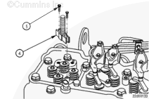
Position the replacer screw (4) above the injector bore and install the two capscrews (5) in the cylinder head where the hold-down clamp capscrews were removed.
NOTE: The valves are not evenly spaced from the injector bore. It is important to align the slots in the valve spring compressor plate with the valve springs.
Apply anti-seize compound to the replacer screw (4) threads. Always read and follow label precautions.
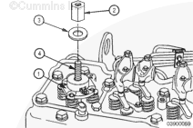
Position the valve spring compressor plate (1) on the replacer screw (4) and align the slots in the valve spring compressor plate with the valve springs.
Install the washer (3) and nut (2) on the replacer screw (4).
Valve springs are under compression and can act as projectiles if released. To reduce the possibility of eye injury, wear safety glasses with side shields.
Turn the nut (2) clockwise to compress the valve springs.
Continue turning the nut (2) clockwise until the valve collets can be removed using a magnetic tool, such as the end of a magnetic screwdriver.
NOTE: Because there is a gap between the top of the piston and the valve face, it may be necessary to use a second magnet to hold the valve stem up to remove the valve collets.
Remove the valve collets and the valve spring compressor service tool.
With the valve collets, valve springs, and valve spring retainers removed, do not rotate the engine. Rotating the engine will allow the valves to drop into the cylinder requiring the cylinder head to be removed or possible engine damage.
Remove the four valve spring retainers and the valve springs.
The same color valve stem seal must be installed in the same location as removed. Incorrect valve stem seals will result in excessive oil consumption and internal engine damage.
CAUTION
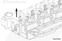
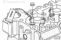
Lubricate all the valve guide bores and valve stems with SAE 15W-40 engine oil. Failure to lubricate the valve guides and valve stems can result in premature valve guide wear.
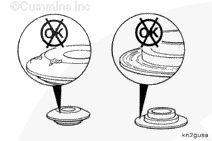
Install new valve stem seals of the same color as removed and in the same location. The black valve guide seals are for the exhaust valves; the blue valve guide seals are for the intake valves.
Lubricate the stems with SAE 15W-40 engine oil before installing the valve stem seals.
Compress the valve springs using the valve spring compressor service tool, Part Number 3164329.
Position the replacer screw (4) above the injector bore and install the two capscrews (5) in the cylinder head where the hold-down clamp screws were removed.
NOTE: The valves are not evenly spaced from the injector bore. It is important to align the slots in the valve spring compressor plate with the valve springs.
Apply anti-seize compound to the replacer screw (4) threads. Always read and follow label precautions.
Position the valve spring compressor plate (1) on the replacer screw (4) and align the slots in the valve spring compressor plate with the valve springs.
Install the washer (3) and nut (2) on the replacer screw (4).
Valve springs are under compression and can act as projectiles if released. To reduce the possibility of eye injury, wear safety glasses with side shields.
NOTE: Because there is a gap between the top of the piston and the valve face, it may be necessary to use a second magnet to pull the valve stem up to remove the valve collets.
Compress the valve springs until the valve collets can be installed.
Install the valve collets.
Service Tip: Use assembly lubricant, Part Number 3163087 or equivalent, on the valve collets to help hold them in place until the valve spring compressor is released.
Using the marks made previously on the vibration damper, rotate the engine to the next mark to replace the valve guide seals on the next pair of cylinders.
To reduce the possibility of personal injury, wear eye protection. If the collets are not correctly installed, they can fly out when the stems are hit with a hammer.
CAUTION
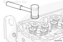
Rotate the engine to the next cylinder in the firing order before hitting the valve stem of the cylinder previously worked on. This will ensure the valve does not contact the piston, resulting in a bent valve and internal engine damage.
After rotating the engine to the next cylinder in the firing order, hit the valve stems of the cylinder previously worked on with a plastic hammer to make sure the collets are seated.
Repeat the previous steps until all of the valve stem seals have been replaced.
Batteries can emit explosive gases. To reduce the possibility of personal injury, always ventilate the compartment before servicing the batteries. To reduce the possibility of arcing, remove the negative (-) battery cable first and attach the negative (-) battery cable last.
Hello, I'm Jack, a diesel engine fan and a blogger. I write about how to fix and improve diesel engines, from cars to trucks to generators. I also review the newest models and innovations in the diesel market. If you are interested in learning more about diesel engines, check out my blog and leave your feedback.
View all posts by Jack


 WARNING


 CAUTION
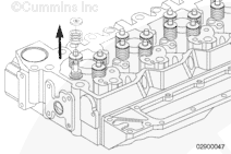


;)
;)
;)
;)
;)
;)
;)
;)
;)
;)
;)
;)
;)
;)
;)
;)
;)
;)
;)
;)
;)
;)
;)
;)
;)
;)
;)
;)
;)
;)