Wear appropriate eye and face protection when using compressed air. Flying debris and dirt can cause personal injury.
WARNING
Do not remove the pressure cap from a hot engine. Wait until the coolant temperature is below 50°C [120°F] before removing the pressure cap. Heated coolant spray or steam can cause personal injury.
WARNING
Coolant is toxic. Keep away from children and pets. If not reused, dispose of in accordance with local environmental regulations.
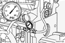
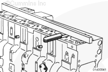
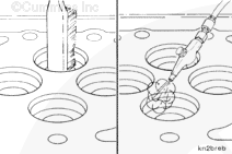
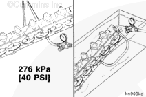
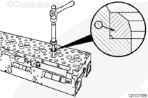
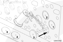
If troubleshooting coolant in the fuel, fuel in the coolant, fuel in the oil, or oil in the fuel, pressurize the internal fuel drain line in the cylinder head and check for leaks.
Connect a regulated air supply hose to the cylinder head fuel drain port with a shut off valve on the air supply side of the pressure gauge.
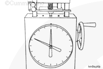
Apply air pressure.
Air Pressure
kpa
psi
276
NOM
30
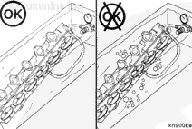
Shut off the air supply to the fuel drain port and monitor the pressure gauge reading. The pressure should hold steady. If the pressure drops rapidly, check for leaks around:
Test fittings
Fuel connectors at the cylinder head
Remove the radiator cap and check for air bubbles in the cooling system.
If the source of the leak can not be determined, remove the cylinder head and pressure test the complete cylinder head. See the Pressure Test step of this procedure. Replace the cylinder head if necessary.
Batteries can emit explosive gases. To reduce the possibility of personal injury, always ventilate the compartment before servicing the batteries. To reduce the possibility of arcing, remove the negative (-) battery cable first and attach the negative (-) battery cable last.
WARNING
Do not remove the pressure cap from a hot engine. Wait until the coolant temperature is below 50°C [120°F] before removing the pressure cap. Heated coolant spray or steam can cause personal injury.
WARNING
Coolant is toxic. Keep away from children and pets. If not reused, dispose of in accordance with local environmental regulations.
CAUTION
Use caution when disconnecting or removing fuel lines, replacing filters and priming the fuel system that fuel is not spilled or drained into the bilge area. Do not drop or throw filter elements into the bilge area. The fuel and fuel filters must be discarded in accordance with local environmental regulations.
CAUTION
Use caution when draining the coolant system that coolant is not spilled or drained into the bilge area. Do not drop or throw filter elements into the bilge area. The coolant and coolant filters must be discarded in accordance with local environmental regulations.
Shut off the sea water supply, if applicable. Refer to the OEM service manual.
Shut off the fuel supply and drain valves. Refer to the OEM service manual.
NOTE: This next step applies to QSL9 engines only. The expansion tank and heat exchanger on the QSC8.3 engines are a one-piece unit. Refer to Procedure 008-053 in Section 8.
This component or assembly weighs greater than 23 kg [50 lb]. To prevent serious personal injury, be sure to have assistance or use appropriate lifting equipment to lift this component or assembly.
Remove the cylinder head capscrews.
Measurements
kg
lb
Cylinder Head Weight
71.2
157
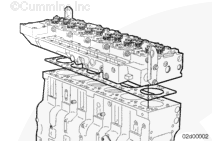
Remove the cylinder head and gasket from the cylinder block.
NOTE: If a leaking valve is suspected, use valve vacuum tester, Part Number 3824277, and cup, Part Number ST-1247-6, to vacuum test the valves and valve seats. The vacuum must not drop more than 254 mm Hg [10 in Hg] in 10 seconds.
Valve to Valve Seat Vacuum
457 mm Hg
Used
18 in Hg
635 mm Hg
New
25 in Hg
NOTE: If a vacuum tester is not available, use a lead pencil or Dykem™ marking pen with the valve removed to mark across the valve face. Install the valve in the valve guide. Hold the valve against the valve seat and rotate the valve backward and forward three or four times. Correct contact against the valve seat will break the marks on the valve face.
If out of specification, disassemble the cylinder head and inspect for damaged valves and/or valve seat inserts. Repair as necessary:
Clean the valve/valve seat inserts and lap the valves.
Replace the damaged valve/valve seat inserts (if available).
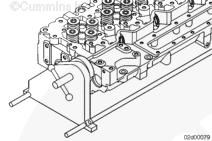
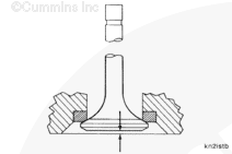
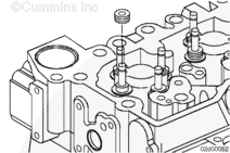
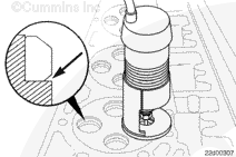
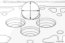
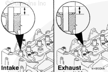
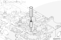
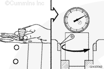
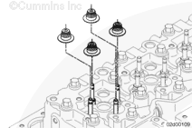
Before removing the injectors, use gauge block, Part Number 3164438, to measure the injector protrusion.
Place the injector protrusion tool on the flat surface of the head. Measure the injector protrusion to the highest point on the injector. The protrusion must be within the following specifications:
Injector Protrusion (CAPS Fuel System)
mm
in
2.60
MIN
0.102
3.40
MAX
0.134
Injector Protrusion (Cummins® Common Rail Fuel System)
If the sealing washer is the correct thickness, check to make sure the injector bore is clean and free of debris. Also make sure that sealing washers are not “stacked” in the injector bore.
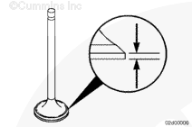
If the valve recess is outside of the specifications, replace the valve. If the valve recess is still outside the specifications, the valve seat insert or cylinder head must be replaced.
If the valve recess is outside of the specifications, replace the valve. If the valve recess is still outside the specifications, the valve seat insert or cylinder head must be replaced.
Keep the valves in a labeled rack for a correct match with companion seats while making measurements.
Mark the valves to identify their location. Any numbering system can be used as long as the valves are put back in their original location if they are to be reused.
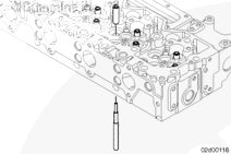
NOTE: Prior to removing the valve guide, reference the Inspect for Reuse section in this procedure. The condition of the valve guide will help to determine if it needs to be replaced.
Use valve guide driver, Part Number 3163101, to remove the old valve guides.
NOTE: Prior to the removal of the valve seat inserts, reference the Clean and Inspect for Reuse section in this procedure. The condition of the valve, the amount of recess, and the sealing of the valve on the seat insert all help to determine if a valve seat insert needs to be replaced.
If required, remove the valve seat inserts.
Inspect the valve-insert-to-cylinder-head contact area. A sufficient groove for the remover must exist.
If there is sufficient valve seat insert groove area, proceed to the next step.
If the valve seat insert groove area is not sufficient, use the valve seat insert cutting kit, Part Number 3376405, to create a sufficient groove.
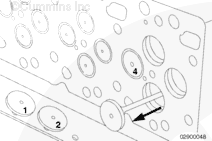
Use the slide hammer remover, Part Number 3376617, with intake valve seat insert extractor, Part Number 3165113 and exhaust valve seat insert extractor, Part Number 3165114, to remove the valve seat inserts.
NOTE: Make certain the valve seat insert remover assembly is perpendicular to the cylinder head when installed. Place the valve seat insert remover assembly into the valve seat insert and rotate the t-handle clockwise until the remover loosely grips the valve seat insert.
Position the valve seat insert remover assembly into the valve seat insert groove area. Tighten the t-handle firmly, allowing the remover to expand under the valve seat insert or into the cut groove.
Strike the slide hammer remover against the top nut until the valve seat insert is removed. Turn the t-handle counterclockwise to release the valve seat insert from the remover.
When using solvents, acids, or alkaline materials for cleaning, follow the manufacturer’s recommendations for use. Wear goggles and protective clothing to reduce the possibility of personal injury.
WARNING
Some solvents are flammable and toxic. Read the manufacturer’s instructions before using.
WARNING
Wear appropriate eye and face protection when using compressed air. Flying debris and dirt can cause personal injury.
WARNING
Wear protective eye covering while cleaning carbon deposits to prevent injury.
Clean the buildup of deposits from the coolant passages. Excessive deposits can be cleaned in an acid tank, but the expansion plugs must first be removed.
Clean the cylinder head combustion deck with an abrasive pad, Part Number 3823258, or equivalent, and diesel fuel or solvent. The surface finish (RA – roughness average) maximum is 3.2 µm [0.0001 in].
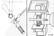
Clean carbon deposits from the valve pockets with a high quality steel wire wheel installed in a drill or a die grinder.
NOTE: An inferior quality wire wheel will lose steel bristles during operation, causing additional contamination.
Wash the cylinder head in a hot, soapy water solution.
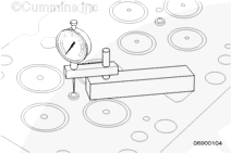
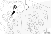
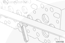
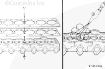
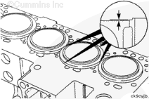
Use a straight edge, Part Number 4918219, and a feeler gauge to measure the overall flatness of the cylinder block.
The overall flatness, end to end and side to side, must not exceed 0.075 mm [0.003 in].
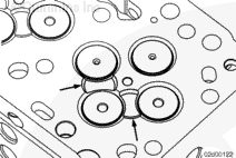
Use a 2-foot straight edge and a 0.0254 mm [0.001 in] feeler gauge to measure local cylinder block combustion surfaces flatness. Check between the cylinder bores and also between the coolant passages. If the 0.0254 mm [0.001 in] feeler gauge fits under the 2-foot straight edge, or if the cylinder block is pitted, has grooves or other damage, the cylinder block must be replaced.
When using solvents, acids, or alkaline materials for cleaning, follow the manufacturer’s recommendations for use. Wear goggles and protective clothing to reduce the possibility of personal injury.
WARNING
Wear appropriate eye and face protection when cleaning the valves. Flying debris and dirt can cause personal injury.
Use a wire brush and solvent to clean the deposits from the valve seat insert bores, if it was necessary to remove the valve seat inserts.
If the valve seat insert was removed in the Disassemble section, measure the inside diameter of the valve seat insert bore in the cylinder head.
Cylinder Head Insert Bore Inside Diameter (ID)
mm
in
39.371
MIN
1.550
39.401
MAX
1.551
NOTE: Before cutting the cylinder head, verify the valve seat inserts are available for the engine being serviced. If none are available, the cylinder head must be replaced.
If out of specification, the valve seat insert bore can be oversized 0.254 mm [0.010 in].
Cylinder Head Insert Bore Inside Diameter (ID) for Oversized Seats
mm
in
39.625
MIN
1.560
39.655
MAX
1.561
NOTE: It is very important to take precise measurements of the valve seat pocket diameter. A 4-point contact gauge is recommended for this measurement process. Failure to take proper diameter measurements will lead to a poor press fit of the valve seat, which may lead to a dropped valve seat and damage to the cylinder head combustion face.
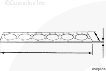
Use a straight edge, Part Number 4918219, and a feeler gauge to inspect the cylinder head combustion surface for flatness.
Cylinder Head Flatness
mm
in
End to End
0.203
MAX
0.008
Side to Side
0.075
MAX
0.003
Use a 2-foot straight edge and a 0.0254 mm [0.001 in] feeler gauge to measure local cylinder head combustion surface flatness. Check between the cylinder bores and also between the coolant passages. If the 0.0254 mm [0.001 in] feeler gauge fits under the 2-foot straight edge or if the cylinder head is pitted, has grooves or other damage, the cylinder head must be replaced.
When using solvents, acids, or alkaline materials for cleaning, follow the manufacturer’s recommendations for use. Wear goggles and protective clothing to reduce the possibility of personal injury.
WARNING
Some solvents are flammable and toxic. Read the manufacturer’s instructions before using.
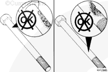
Clean the valve heads with a soft wire wheel.
NOTE: Keep the valves in a labeled rack to prevent mixing prior to making measurements.
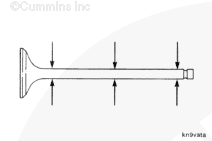
Polish the valve stems with an abrasive pad, Part Number 3823258, or equivalent, and diesel fuel or solvent.
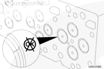
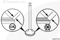
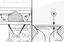
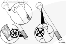
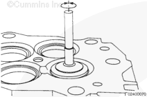
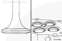
Verify the valve sealing area is in the center of the valve. If the sealing area extends to the top or bottom of the valve, the valve must be replaced.
After replacing the valve, recheck the valve sealing area. If the sealing area still extends to the top or bottom of the valve, the valve seat must be replaced.
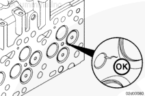
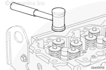
Use a lead pencil or Dykem™ marking pen to mark across the valve face. Install the valve in the valve guide. Hold the valve against the valve seat and rotate the valve backward and forward three or four times. Correct contact against the valve seat will break the marks on the valve face.
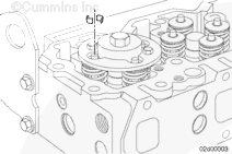
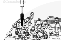
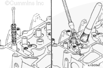
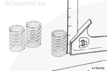
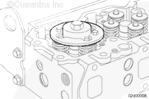
A load of 906 to 1007 N [204 to 226 lbf] is required to compress the spring to a height of 30.6 mm [1.20 in]. Use spring compressor tool, Part Number 3375182, to measure spring force.
Replace the valve spring if the load required to compress the spring is outside the specification.
When using solvents, acids, or alkaline materials for cleaning, follow the manufacturer’s recommendations for use. Wear goggles and protective clothing to reduce the possibility of personal injury.
WARNING
Some solvents are flammable and toxic. Read the manufacturer’s instructions before using.
Use a petroleum-based solvent to clean the capscrews.
Clean the capscrews thoroughly with a wire brush or a soft wire wheel. A non-abrasive bead blaster can be used to remove deposits from the shank and the threads.
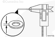
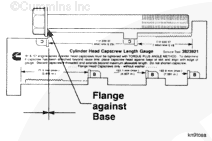
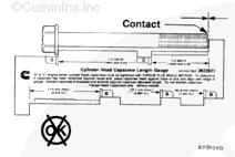
If the end of the capscrew touches the foot of the gauge, the capscrew is too long and must be discarded. The maximum capscrew free length is 162.6 mm [6.4 in].
26 – 180 mm long head capscrews, Part Number 3920781
26 – M12 x 1.75 hexagon flange nuts
52 – 12 mm washers, Part Number 3900269
Place a washer between each capscrew and the head, and between each nut and test plate. This will prevent mutilation on the surface of the cylinder head.
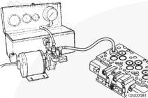
This component or assembly weighs greater than 23 kg [50 lb]. To prevent serious personal injury, be sure to have assistance or use appropriate lifting equipment to lift this component or assembly.
Connect a regulated air supply hose to the test fixture plate.
Apply air pressure.
Measurements
kpa
psi
Air Pressure
276
40
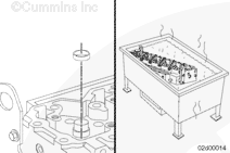
Use a nylon lifting strap and hoist to place the cylinder head in a tank of heated water.
Measurements
celsius
fahrenheit
Water Temperature
60
140
The cylinder head must be completely submerged in the water.
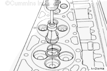
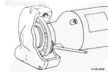
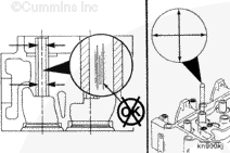
Measure the valve-seat-to-valve-guide runout. Use arbor set, Part Number 3823186, and eccentrimeter, Part Number ST-685-4, or equivalent.
Valve-Seat-to-Valve-Guide Runout
mm
in
0.2
MAX
0.008
If the valve-seat-to-valve-guide runout is not within specifications, one of the following actions can be taken:
Apply Dykem™ marking pen to the valve seat and valve seating surfaces and allow to dry. Install the valve in the valve guide. Hold the valve against the valve seat, and rotate the valve backward and forward three to four times. Verify the contact against the valve seat forms a uniform band on the valve sealing surface. If a uniform band is formed, the assembly is within specifications.
Clean the valve/valve seat and lap the valves.
Remove the valve seat and make sure no debris is causing an issue under the seat. Reinstall the valve seat if debris is found.
Remove the valve seat and machine the valve seat pocket oversize so that an oversize valve seat can be installed. Reference the Clean and Inspect for Reuse section above for valve seat pocket diameter specifications. Use the valve guide ID during machining to help position the valve seat pocket to valve guide ID, to make sure of a proper runout measurement after the oversize valve seat is installed.
If new valve seat inserts were installed and/or the valve leakage was above specification, the valve seat/valve can be lapped.
Lubricate the stems with SAE 15W-40 engine oil before installing the valves.
Use a fine lapping compound, Part Number 3375805, or equivalent. Apply a thin and even coating on the valve.
Use a power or a hand suction lapping tool to provide pressure in the center of the valve.
Turn the valve backward and forward. Continue lapping until the compound shows a continuous contact pattern on both the valve seat insert and the valve.
If the valve recess is outside the specifications, replace the valve. If the valve recess is still outside the specifications, the valve seat insert or cylinder head must be replaced.
If the valve recess is outside of the specifications, replace the valve. If the valve recess is still outside the specifications, the valve seat insert or cylinder head must be replaced.
Before installing the cylinder head, vacuum test the cylinder head again. Reference the information above in the Vacuum Test section of this procedure.
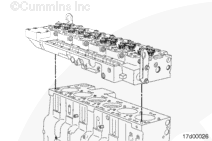
This component or assembly weighs greater than 23 kg [50 lb]. To prevent serious personal injury, be sure to have assistance or use appropriate lifting equipment to lift this component or assembly.
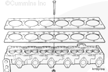
Carefully put the cylinder head straight down onto the cylinder block, and seat it onto the dowels.
If new capscrews are used, capscrew threads are to be burnished. To burnish new capscrews, tighten the capscrews as described below. Loosen the capscrews and repeat the tightening sequence.
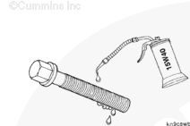
Lubricate the threads and under the heads on the cylinder head capscrews with clean 15W-40 engine lubricating oil.
Coolant is toxic. Keep away from children and pets. If not reused, dispose of in accordance with local environmental regulations.
WARNING
Wear appropriate eye and face protection when using compressed air. Flying debris and dirt can cause personal injury.
WARNING
Batteries can emit explosive gases. To reduce the possibility of personal injury, always ventilate the compartment before servicing the batteries. To reduce the possibility of arcing, remove the negative (-) battery cable first and attach the negative (-) battery cable last.
NOTE: This next step applies to QSL9 engines only. The expansion tank and heat exchanger on the QSC8.3 engines are a one-piece unit. Refer to Procedure 008-053 in Section 8.
Hello, I'm Jack, a diesel engine fan and a blogger. I write about how to fix and improve diesel engines, from cars to trucks to generators. I also review the newest models and innovations in the diesel market. If you are interested in learning more about diesel engines, check out my blog and leave your feedback.
View all posts by Jack
 WARNING


 CAUTION
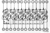


;)
;)
;)
;)
;)
;)
;)
;)
;)
;)
;)
;)
;)
;)
;)
;)
;)
;)
;)
;)
;)
;)
;)
;)
;)
;)
;)
;)
;)
;)
;)
;)
;)
;)
;)
;)
;)
;)
;)
;)
;)
;)
;)
;)
;)
;)
;)
;)
;)
;)
;)
;)
;)
;)
;)
;)
;)
;)
;)
;)
;)
;)
;)
;)
;)
;)
;)
;)
;)
;)
;)
;)
;)
;)
;)
;)
;)
;)
;)
;)
;)
;)
;)
;)
;)
;)
;)
;)
;)
;)
;)
;)
;)
;)
;)
;)
;)
;)
;)
;)
;)
;)
;)
;)
;)
;)
;)
;)
;)
;)
;)
;)
;)
;)