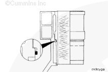
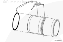
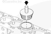
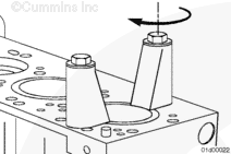
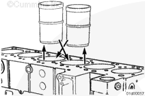
The cylinder block has a replaceable cylinder liner. A mid-stop design is used to locate the liner in the block. A press fit between the liner and the block provides coolant sealing at the top of the liner. A rectangular ring seal (liner seal) is used for sealing at the mid-stop portion of the liner.
NOTE: Cummins Inc. does not recommend removing the cylinder liners to repair an oil consumption problem if the inside diameters of the liners are within the inspection limits included in this procedure. Careful analysis of the condition of the liner bores, piston rings, and pistons can result in the restoration of cylinder sealing with a minimum replacement of parts.
Batteries can emit explosive gases. To reduce the possibility of personal injury, always ventilate the compartment before servicing the batteries. To reduce the possibility of arcing, remove the negative (-) battery cable first and attach the negative (-) battery cable last.
WARNING
Do not remove the pressure cap from a hot engine. Wait until the coolant temperature is below 50°C [120°F] before removing the pressure cap. Heated coolant spray or steam can cause personal injury.
WARNING
Coolant is toxic. Keep away from children and pets. If not reused, dispose of in accordance with local environmental regulations.
WARNING
To reduce the possibility of personal injury, avoid direct contact of hot oil with your skin.
WARNING
Some state and federal agencies have determined that used engine oil can be carcinogenic and cause reproductive toxicity. Avoid inhalation of vapors, ingestion, and prolonged contact with used engine oil. If not reused, dispose of in accordance with local environmental regulations.
Batteries can emit explosive gases. To reduce the possibility of personal injury, always ventilate the compartment before servicing the batteries. To reduce the possibility of arcing, remove the negative (-) battery cable first and attach the negative (-) battery cable last.
WARNING
Do not remove the pressure cap from a hot engine. Wait until the coolant temperature is below 50°C [120°F] before removing the pressure cap. Heated coolant spray or steam can cause personal injury.
WARNING
Coolant is toxic. Keep away from children and pets. If not reused, dispose of in accordance with local environmental regulations.
WARNING
To reduce the possibility of personal injury, avoid direct contact of hot oil with your skin.
WARNING
Some state and federal agencies have determined that used engine oil can be carcinogenic and cause reproductive toxicity. Avoid inhalation of vapors, ingestion, and prolonged contact with used engine oil. If not reused, dispose of in accordance with local environmental regulations.
CAUTION
Use caution when disconnecting or removing fuel lines and replacing filters that fuel is not spilled or drained into the bilge area. Do not drop or throw filter elements into the bilge area. The fuel and fuel filters must be discarded in accordance with local environmental regulations.
CAUTION
Use caution when draining the coolant. Do not spill coolant into the bilge area. Coolant must not be pumped overboard. The coolant must be disposed in accordance with local environmental regulations.
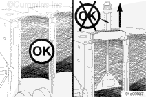
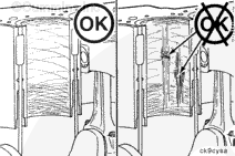
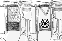
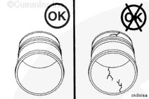
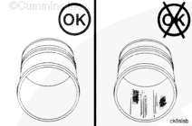
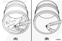
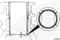
Inspect the inside diameter for liner bore polishing.
A moderate polish produces a bright mirror finish in the worn area with traces of the original hone marks or an indication of an etch pattern.
A heavy polish produces a bright mirror finish in the worn area with no traces of hone marks or an etch pattern.
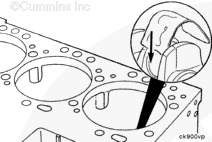
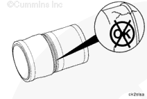
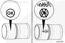
Do not reuse liners exhibiting heavy polish or any indications of particle embedment from a failure. Severely worn liners will have a ridge near the top of the liner bore.
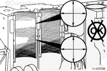
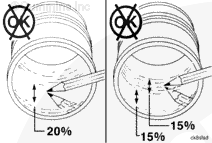
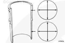
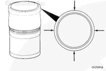
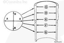
If the wear pattern indicates the liner bore is not straight or not round, use a dial bore gauge to measure the liner inside diameter in four places 90 degrees apart at the top and bottom of the piston travel area.
NOTE: If a liner bore is not acceptable for reuse, it must be replaced. Damaged liners can not be honed or deglazed. This would destroy the cross-hatch pattern needed for oil control.
NOTE: Do not remove or disturb the liner seals for liners which pass the inspection criteria.
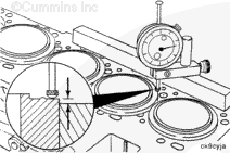
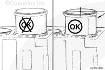
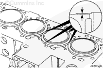
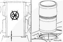
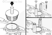
Liner protrusion is the distance the liner protrudes above the block face. Before removing the liners, check the protrusion in the “unclamped” stage. Use liner protrusion gauge, Part Number 3164438, to measure the liner protrusion.
Cylinder Liner Protrusion
mm
in
0.026
MIN
0.0010
0.122
MAX
0.0048
If the liner was installed correctly and the liner protrusion is out of limits, it will be necessary to machine the counterbore and add shims to restore to the original specifications.
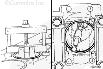
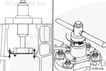
The liner puller must be installed and used as described to avoid damage to the cylinder block. The puller must not contact the block casting at points (1), (2), (3), and (4).
Universal Cylinder Liner Puller Method
Cylinder Liner Puller, Part Number 3376015
Insert the liner puller into the top of the cylinder block.
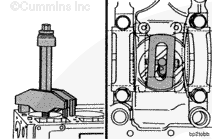
The liner puller must be installed and used as described to reduce the possibility of damage to the cylinder block. The puller plate must be parallel to the main bearing saddles and must not overlap the liner outside diameter.
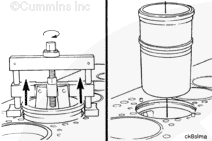
Standard Liner Puller Method
Liner Puller, Part Number 3163745, may be used as an alternative to the standard puller. The universal puller must be used with remover plate, Part Number 3822786.
Insert the liner puller into the top of the cylinder block.
When using a steam cleaner, wear safety glasses or a face shield, as well as protective clothing. Hot steam can cause serious personal injury.
WARNING
When using solvents, acids, or alkaline materials for cleaning, follow the manufacturer’s recommendations for use. Wear goggles and protective clothing to reduce the possibility of personal injury.
WARNING
Some solvents are flammable and toxic. Read the manufacturer’s instructions before using.
WARNING
Wear appropriate eye and face protection when using compressed air. Flying debris and dirt can cause personal injury.
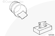
Use solvent or steam clean the liners and dry with compressed air.
Use clean 15W-40 oil to lubricate the inside diameter of the liners.
Allow the oil to soak in the liner for 5 to 10 minutes.
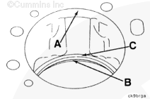
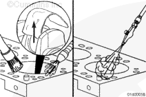
Clean all deposits and debris from sealing surfaces A, B, and C. Use abrasive pad, Part Number 3823258 or equivalent, and cleaning solvent to polish the surfaces. Due to the critical machined tolerances, care should be taken not to remove any additional material.
If surface C has cracks or signs of extreme wear, the counterbore will require machining and the installation of shims for the correct liner protrusion.
When using solvents, acids, or alkaline materials for cleaning, follow the manufacturer’s recommendations for use. Wear goggles and protective clothing to reduce the possibility of personal injury.
WARNING
Some solvents are flammable and toxic. Read the manufacturer’s instructions before using.
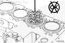
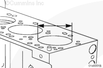
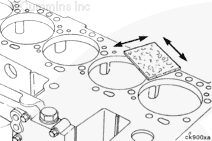
Clean the combustion deck with a gasket scraper or abrasive pad, Part Number 3823258 or equivalent, and diesel fuel or solvent.
When using solvents, acids, or alkaline materials for cleaning, follow the manufacturer’s recommendations for use. Wear goggles and protective clothing to reduce the possibility of personal injury.
WARNING
Some solvents are flammable and toxic. Read the manufacturer’s instructions before using.
WARNING
Wear appropriate eye and face protection when using compressed air. Flying debris and dirt can cause personal injury.
Thoroughly flush the block with mineral spirits or cleaning solvent.
Remove the shop rags and clean the crankshaft with a cleaning solvent.
Blow the cylinder bores and crankshaft dry and wipe them clean with a lint-free cloth.
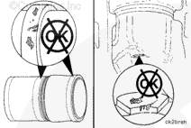
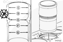
When reusing liners, install them in the same cylinder from where they were removed and rotate them 45 degrees (1/8 turn) from their original position. When correctly installed, any liner pitting must be positioned as illustrated so the pitted surface is rotated away from the location where pitting occurs.
Service Tip: If the out-of-limit condition is minimal, tolerance stack-up may allow the protrusion limits to be obtained by installing other new liners in the out-of-limit bore.
Measure the liner bore for out-of-roundness at points “C”, “D”, “E”, “F”, and “G”. Measure each point in the direction “AA” and “BB”. The bore must not be more than 0.04 mm [0.002 in] out-of-round.
Batteries can emit explosive gases. To reduce the possibility of personal injury, always ventilate the compartment before servicing the batteries. To reduce the possibility of arcing, remove the negative (-) battery cable first and attach the negative (-) battery cable last.
Batteries can emit explosive gases. To reduce the possibility of personal injury, always ventilate the compartment before servicing the batteries. To reduce the possibility of arcing, remove the negative (-) battery cable first and attach the negative (-) battery cable last.
Hello, I'm Jack, a diesel engine fan and a blogger. I write about how to fix and improve diesel engines, from cars to trucks to generators. I also review the newest models and innovations in the diesel market. If you are interested in learning more about diesel engines, check out my blog and leave your feedback.
View all posts by Jack

 WARNING
 CAUTION






;)
;)
;)
;)
;)
;)
;)
;)
;)
;)
;)
;)
;)
;)
;)
;)
;)
;)
;)
;)
;)
;)
;)
;)
;)
;)
;)
;)
;)
;)
;)
;)
;)
;)
;)
;)
;)
;)
;)
;)
;)
;)
;)
;)
;)
;)
;)
;)
;)
;)
;)
;)
;)
;)
;)
;)
;)
;)
;)
;)
;)
;)
;)
;)
;)
;)
;)
;)
;)
;)
;)
;)
;)
;)
;)
;)
;)
;)
;)
;)
;)
;)
;)
;)
;)
;)
