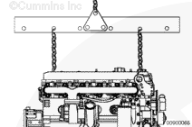
The engine lifting equipment must be designed to lift the engine and transmission as an assembly without causing personal injury.
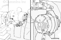
Install all accessories and brackets that were removed from the previous engine.
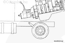
NOTE: On applications where the rear engine mounts are attached to the transmission, it will often be necessary to install the engine and transmission as an assembly.
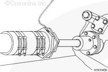
Use a properly rated hoist and engine lifting fixture, attached to the engine-mounted lifting brackets, to install the engine.
Remove all tags on all hoses, lines, linkages and electrical connections.
NOTE: Make sure all lines, hoses and tubes are properly routed and fastened to prevent damage. Make sure the air intake and exhaust pipe connections are tight and free of leaks.
NOTE: Installations can vary from OEM to OEM. See Marine Recreational B and C Installation Directions, Bulletin 3884649 for more detailed instructions for various engine and application.
NOTE: Some of the graphics used in this procedure will not match all applications, but the procedure is the same unless otherwise noted.
Install all accessories, brackets, and drive units that were removed from the engine, if the engine is being replaced.
The engine lifting equipment must be designed to lift the engine and transmission safely as an assembly without causing personal injury. The dry weight of the standard QSC8.3 marine engine is 896 kg [1975 lb]. The dry weight of the standard QSL9 marine engine is 907 kg [2000 lb].
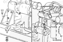
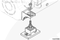
Align the engine in the vessel and tighten the engine mounting capscrews. Refer to the OEM service manual for torque specifications.
See Marine Recreational B and C Installation Directions, Bulletin 3884649.
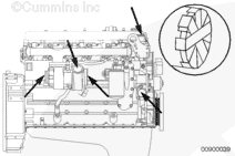
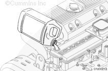
Connect all engine and vessel-mounted components accessories.
Make sure all sea water lines, fuel lines, hoses, and tubes are properly routed and fastened to prevent damage. Make sure the exhaust pipe connections are tight and free of leaks.
NOTE: The total coolant capacity of the engines varies. Refer to the OEM service manual to determine the capacity of the whole cooling system.
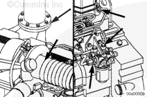
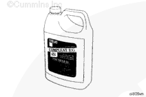
Fill the cooling system with new coolant. Cummins Inc. recommends using Fleetguard® Compleat. It is available in both glycol forms (ethelyne and propylene). Refer to Procedure 008-018 in Section 8.
See the engine data sheet to determine the capacity of the whole cooling system.
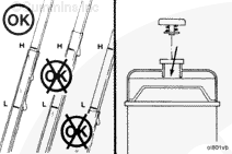
Leave the pressure cap off or loose until air can be purged out of the cooling system. Improper purging of air from the cooling system will result in engine damage from overheating. If the vessel is equipped with a cabin heater, remote heat exchanger units, or if the engine is keel cooled, it will take longer for the trapped air to purge.
Perform a final inspection to make sure all hoses, wires, linkages, and components have been properly installed and tightened.
Make sure all alarms and lights are working prior to starting the engine.
To prevent damage to the sea water pump, open the sea water valves before engaging the starting motor. Rotation of the sea water pump impeller with no water can damage the impeller.
If the engine is cooled by a heat exchanger, open the sea water supply lines.
NOTE: This procedure will cause fault codes to be logged in the electronic control module (ECM). These faults will need to be removed prior to placing the engine in service. Refer to Section TF of Troubleshooting and Repair Manual, ISB, QSB4.5, QSB5.9, QSB6.7, ISC, QSC8.3, ISL, and QSL9 Engines, CM850 Electronic Control System, Bulletin 4021416.
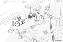
Disconnect the engine injector harness connectors at the rocker housing to make sure the engine will not start.
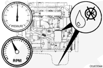
Do not engage the starting motor for more than 30 seconds. To reduce the possibility of engine damage, wait two minutes between starter engagements to cool the starting motor.
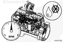
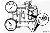
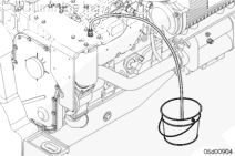
Crank the engine until the lubricating oil pressure gauge indicates a positive pressure.
Use caution when disconnecting or removing fuel lines, replacing filters and priming the fuel system that fuel is not spilled or drained into the bilge area. Do not drop or throw filter elements into the bilge area. The fuel and fuel filters must be discarded in accordance with local environmental regulations.
Do not remove the pressure cap from a hot engine. Wait until the coolant temperature is below 50°C [120°F] before removing the pressure cap. Heated coolant spray or steam can cause personal injury.
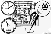
Operate the engine and check for sea water flow. Be sure the marine gear is in neutral and the engine can shift in and out of gear.
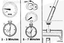
Operate the engine at low idle for two to three minutes.
Shut off the engine and wait five to seven minutes for the lubricating oil to drain to the lubricating oil pan.
Check the lubricating oil and coolant levels again.
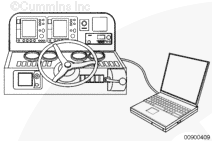
Use INSITE™ electronic service tool to read and clear any fault codes.
Refer to Section TF of the Troubleshooting and Repair Manual, ISB, QSB4.5, QSB5.9, QSB6.7, ISC, QSC8.3, ISL, and QSL9 Engines, CM850 Electronic Control System, Bulletin 4021416, to correct any fault codes.
Hello, I'm Jack, a diesel engine fan and a blogger. I write about how to fix and improve diesel engines, from cars to trucks to generators. I also review the newest models and innovations in the diesel market. If you are interested in learning more about diesel engines, check out my blog and leave your feedback.
View all posts by Jack
 WARNING


 CAUTION
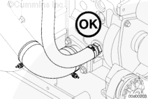
;)
;)
;)
;)
;)
;)
;)
;)
;)
;)
;)
;)
;)
;)
;)
;)
;)
;)
;)
;)
;)
;)
;)
;)
;)
;)
;)
;)
;)
;)
;)
;)
;)
;)
;)
;)
;)
;)
;)
;)
;)
;)