Batteries can emit explosive gases. To reduce the possibility of personal injury, always ventilate the compartment before servicing the batteries. To reduce the possibility of arcing, remove the negative (-) battery cable first and attach the negative (-) battery cable last.
WARNING
Wear appropriate eye and face protection when using compressed air. Flying debris and dirt can cause personal injury.
WARNING
When using a steam cleaner, wear safety glasses or a face shield, as well as protective clothing. Hot steam can cause serious personal injury.
CAUTION
Clean all fittings before disassembly. Dirt or contaminants can damage the fuel system.
Before servicing any fuel system components, (such as fuel lines, fuel pump, injectors, etc.) which would expose the fuel system or internal engine component to potential contaminants prior to disassembly, clean the fittings, mounting hardware, and the area around the component to be removed. Dirt or contaminants can be introduced into the fuel system and engine if the surrounding areas are not cleaned, resulting in damage to the fuel system and engine. Refer to Procedure 000-009 in Section 0.
Normal engine operation creates highly pressurized fuel in the fuel line which will remain in the fuel line after engine shutdown. Never open the fuel system when the engine is operating. Before servicing the fuel system, always loosen the pump to rail fuel line at the rail to vent the pressure. Keep hands clear of the line when loosening. High pressure fuel spray can penetrate the skin, resulting in serious personal injury or death.
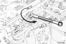
Before servicing the fuel system, loosen the pump to rail line at the rail to vent the pressure.
Keep hands clear of the line when loosening.
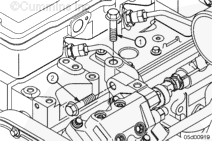
Tighten the fuel rail nut.
Torque Value: 65 n.m [48 ft-lb]
NOTE: A machined slot in this fitting directs the fuel spray towards the engine block.
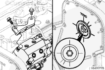
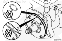
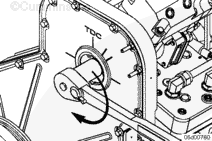
Locate top dead center for cylinder Number 1 by barring the engine until the line on the fuel pump gear aligns with the front cover mark for top dead center.
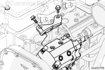
NOTE: Depending on the build year of the engine, the fuel pump support bracket can be mounted on the fuel pump head or the fuel pump actuator housing.
Make sure the engine is at Number 1 cylinder, top dead center. The fuel pump gear timing mark must align with the top dead center mark on the front cover.
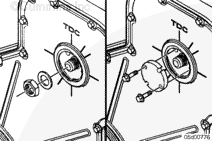
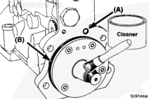
Make certain the o-ring seals for the oil feed orifice (A) and pilot (B) are correctly installed.
Lubricate the pilot o-ring (B) with clean engine oil.
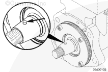
Clean the nose of the drive shaft and the fuel pump gear inside diameter with contact cleaner, Part Number 3824510 or equivalent.
The fuel pump drive gear inside diameter and the drive shaft outside diameter must be clean and dry before installing the gear.
Hello, I'm Jack, a diesel engine fan and a blogger. I write about how to fix and improve diesel engines, from cars to trucks to generators. I also review the newest models and innovations in the diesel market. If you are interested in learning more about diesel engines, check out my blog and leave your feedback.
View all posts by Jack
 WARNING
  CAUTION


;)
;)
;)
;)
;)
;)
;)
;)
;)
;)
;)
;)
;)
;)
;)
;)
;)
;)
;)
;)
;)
;)