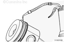
Batteries can emit explosive gases. To reduce the possibility of personal injury, always ventilate the compartment before servicing the batteries. To reduce the possibility of arcing, remove the negative (-) battery cable first and attach the negative (-) battery cable last.
WARNING
To reduce the possibility of personal injury, avoid direct contact of hot oil with your skin.
WARNING
Some state and federal agencies have determined that used engine oil can be carcinogenic and cause reproductive toxicity. Avoid inhalation of vapors, ingestion, and prolonged contact with used engine oil. If not reused, dispose of in accordance with local environmental regulations.
WARNING
Do not remove the pressure cap from a hot engine. Wait until the coolant temperature is below 50°C [120°F] before removing the pressure cap. Heated coolant spray or steam can cause personal injury.
WARNING
Coolant is toxic. Keep away from children and pets. If not reused, dispose of in accordance with local environmental regulations.
When using solvents, acids, or alkaline materials for cleaning, follow the manufacturer’s recommendations for use. Wear goggles and protective clothing to reduce the possibility of personal injury.
WARNING
Some solvents are flammable and toxic. Read the manufacturer’s instructions before using.
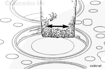
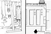
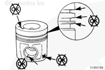
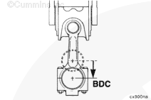
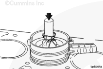
Rotate the crankshaft until the pistons are just below the carbon deposits that are found above the ring travel area.
Use an abrasive pad, Part Number 3823258 or equivalent, and solvent to remove the carbon deposits.
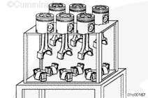
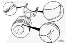
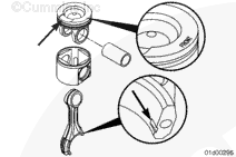
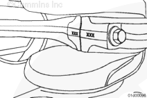
Mark each piston according to the cylinder location.
NOTE: On pistons with anodized coatings, do not stamp on the anodized coating or on the outer rim. Do not stamp on the aluminum piston crown above the piston pin axis.
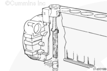
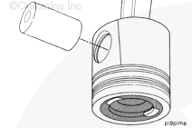
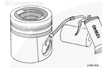
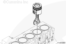
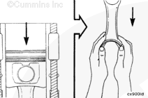
Use both hands to remove the piston and connecting rod assembly.
If parts are reused, the piston and connecting rod assemblies must be installed in the same cylinder locations from which they were removed to provide the proper fit of worn mating surfaces.
Use tags to mark the piston and connecting rod assembly locations as they are removed.
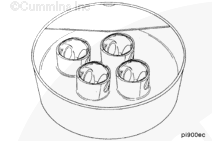
Place the rod and piston assemblies in a container to protect them from damage.
When using solvents, acids, or alkaline materials for cleaning, follow the manufacturer’s recommendations for use. Wear goggles and protective clothing to reduce the possibility of personal injury.
WARNING
Some solvents are flammable and toxic. Read the manufacturer’s instructions before using.
Rotate the crankshaft until the pistons are just below the carbon deposits that are found above the ring travel area.
Use an abrasive pad, Part Number 3823258 or equivalent, and solvent to remove the carbon deposits.
Mark each piston according to the cylinder location.
NOTE: On pistons with anodized coatings, do not stamp on the anodized coating or on the outer rim. Do not stamp on the aluminum piston crown above the piston pin axis.
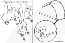
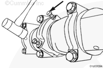
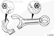
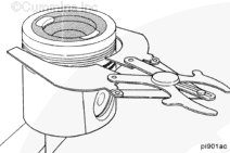
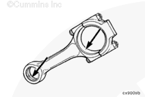
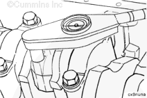
Do not damage the fractured split surface on the connecting rod or connecting rod cap while the connecting rod caps are removed. If the fractured split surface is damaged, the connecting rod and connecting rod cap must be replaced to help reduce the possibility of engine damage. Incorrect assembly can damage the rod.
Remove the connecting rod capscrews.
Remove the rod cap.
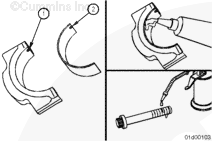
Remove the lower rod bearing.
Mark the cylinder number and the letter “L” (lower) on the flat surface of the bearing tang.
Use both hands to remove the piston and connecting rod assembly.
If parts are reused, the piston and connecting rod assemblies must be installed in the same cylinder location from which they were removed, to provide the proper fit of worn mating surfaces.
Use tags to mark the piston and connecting rod assembly locations as they are removed.
Place the rod and piston assemblies in a container to protect them from damage.
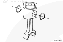
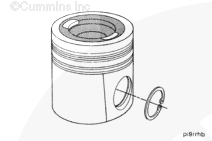
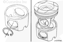
NOTE: When the piston pin is removed from an articulated piston, the skirt will separate from the crown. Use care to prevent damage to the piston.
Mark the number of the cylinder from which the piston, crown, skirt, and pin were removed, on the parts, to make sure they are installed in the correct cylinder location, if they are to be reused.
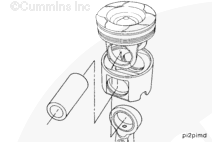
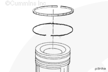
Most piston rings look similar but have significant difference. Make sure the correct part number is being used for the engine.
The top surface of the upper and intermediate rings are identified either with the word “TOP” or a supplier identification mark, such as a dot. Assemble with the word “TOP” or the supplier mark facing upward.
The bottom, or oil control ring, can be installed with either side up.
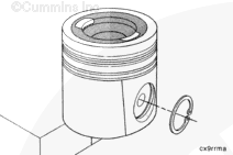
If new bearings are not used, the used bearings must be installed on the same connecting rod and location from where they were removed.
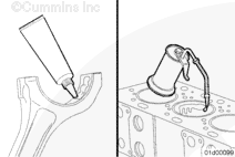
Install the upper bearing shell into the connecting rod.
The tang of the bearing shell must be in the slot of the rod. The end of the bearing shell must be even with the cap mounting surface.
NOTE: The upper and lower rod bearing shells are not interchangeable on angle split connecting rods. The backs of the bearings are marked with either “UPR” or “LWR” to indicate their location.
NOTE: If the connecting rod bushing is removed for any reason, a new bushing must be used.
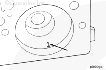
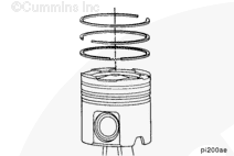
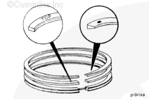
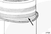
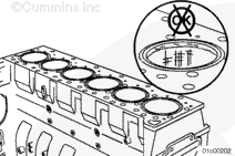
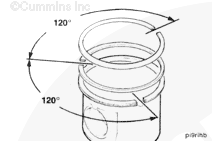
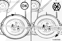
Rotate the rings to position the ring gaps as shown.
NOTE: The ring gap of each ring must not be aligned with the piston pin, or with any other ring. If the ring gaps are not aligned correctly, the rings will not seal properly.
Do not damage the fractured split surface on the connecting rod or connecting rod cap while the connecting rod cap is removed. If the fractured split surface is damaged, the connecting rod and connecting rod cap must be replaced to help reduce the possibility of engine damage.
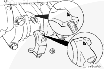
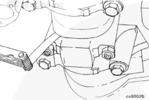
The connecting rod and cap must have the same number and must be installed in the proper cylinder. The connecting rod cap number and rod number must be on the same side of the connecting rod to prevent engine damage during engine operation.
Check for freedom of rotation as the connecting rod caps are installed. If the crankshaft does not rotate freely, check the installation of the connecting rod bearings and the bearing size.
Batteries can emit explosive gases. To reduce the possibility of personal injury, always ventilate the compartment before servicing the batteries. To reduce the possibility of arcing, remove the negative (-) battery cable first and attach the negative (-) battery cable last.
Hello, I'm Jack, a diesel engine fan and a blogger. I write about how to fix and improve diesel engines, from cars to trucks to generators. I also review the newest models and innovations in the diesel market. If you are interested in learning more about diesel engines, check out my blog and leave your feedback.
View all posts by Jack
 WARNING


 CAUTION


;)
;)
;)
;)
;)
;)
;)
;)
;)
;)
;)
;)
;)
;)
;)
;)
;)
;)
;)
;)
;)
;)
;)
;)
;)
;)
;)
;)
;)
;)
;)
;)
;)
;)
;)
;)
;)
;)
;)
;)
;)
;)
;)
;)
;)
;)
;)
;)
;)
;)
;)
;)
;)
;)
;)
;)
;)
;)
;)
;)
;)
;)
;)
;)
;)
;)
;)
;)
;)
;)
;)
;)
;)
;)
;)
;)
;)
;)
;)
;)
;)
;)
;)
;)
;)
;)