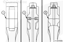
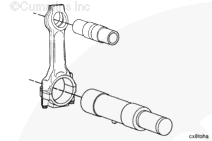
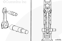
The connecting rod configuration can change, depending on the engine configuration. Some engines use straight split connecting rods. Other engines use angle split connecting rods. The connecting rod can also have a fracture split surface or a serrated surface.
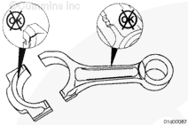
Connecting rods with a fracture split or serrated surface must be treated with caution. The two pieces of the connecting rod can not be rubbed together, as this will damage the mating surfaces. Use care to not drop either piece of the connecting rod.
C connecting rods are straight, with a smooth machined surface.
L fracture split connecting rods are angled, with a fractured surface at the crankshaft end.
L serrated connecting rods are angled with a serrated machined surface at the crankshaft end.
These connecting rods can not be mixed in the same engine.
Batteries can emit explosive gases. To reduce the possibility of personal injury, always ventilate the compartment before servicing the batteries. To reduce the possibility of arcing, remove the negative (-) battery cable first and attach the negative (-) battery cable last.
WARNING
Do not remove the pressure cap from a hot engine. Wait until the coolant temperature is below 50°C [120°F] before removing the pressure cap. Heated coolant spray or steam can cause personal injury.
WARNING
Coolant is toxic. Keep away from children and pets. If not reused, dispose of in accordance with local environmental regulations.
WARNING
To reduce the possibility of personal injury, avoid direct contact of hot oil with your skin.
WARNING
Some state and federal agencies have determined that used engine oil can be carcinogenic and cause reproductive toxicity. Avoid inhalation of vapors, ingestion, and prolonged contact with used engine oil. If not reused, dispose of in accordance with local environmental regulations.
Disconnect the batteries. Refer to the OEM service manual.
When using a steam cleaner, wear safety glasses or a face shield, as well as protective clothing. Hot steam can cause serious personal injury.
WARNING
When using solvents, acids, or alkaline materials for cleaning, follow the manufacturer’s recommendations for use. Wear goggles and protective clothing to reduce the possibility of personal injury.
WARNING
Some solvents are flammable and toxic. Read the manufacturer’s instructions before using.
WARNING
Wear appropriate eye and face protection when using compressed air. Flying debris and dirt can cause personal injury.
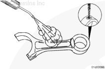
Use a nylon bristle brush to clean the oil drillings.
Use steam or solvent to clean the connecting rods.
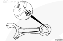
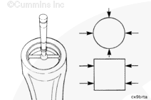
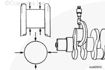
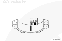
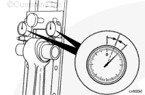
Measure the connecting rod crankshaft bore with the bearing shells removed and the caps tightened to the proper torque value. Refer to Procedure 001-054 in Section 1.
Connecting Rod Crank Bore Diameter (Bearings Removed)
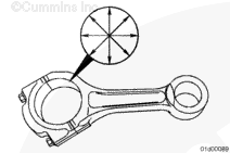
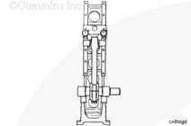
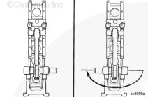
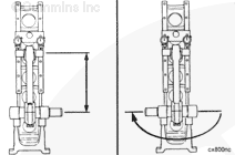
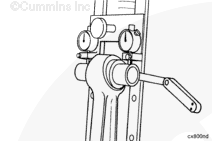
Use a connecting rod checking fixture, Part Number ST-561, and a connecting rod mandrel set, Part Number 3823286, to inspect the bend and twist of the rods.
Calibrate the checking fixture with a new rod that has been measured for correct center to center length, 215.975 to 216.025 mm [8.5029 to 8.5040 in].
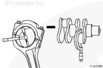
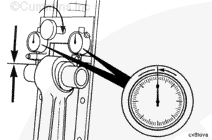
Assemble the connecting rod cap to the rod, as described previously in this procedure.
Check the dial indicators for zero position again.
If the dial indicators show any change from zero adjust the dials to half the indicated reading.
The fixture is now calibrated to allow the connecting rod to be installed into the fixture in either direction and the dials will indicate an equal defection on either side or zero.
Batteries can emit explosive gases. To reduce the possibility of personal injury, always ventilate the compartment before servicing the batteries. To reduce the possibility of arcing, remove the negative (-) battery cable first and attach the negative (-) battery cable last.
Hello, I'm Jack, a diesel engine fan and a blogger. I write about how to fix and improve diesel engines, from cars to trucks to generators. I also review the newest models and innovations in the diesel market. If you are interested in learning more about diesel engines, check out my blog and leave your feedback.
View all posts by Jack
 WARNING


;)
;)
;)
;)
;)
;)
;)
;)
;)
;)
;)
;)
;)
;)
;)
;)
;)
;)
;)
;)
;)
;)
;)
;)
;)
;)
;)
;)
;)
;)
;)
;)
;)
;)
;)
;)