Batteries can emit explosive gases. To reduce the possibility of personal injury, always ventilate the compartment before servicing the batteries. To reduce the possibility of arcing, remove the negative (-) battery cable first and attach the negative (-) battery cable last.
Use one of the following methods to repair any damaged threaded holes:
Chase the threads.
Use the threaded insert kit, Part Number 3822709.
NOTE: A maximum of one front crankshaft threaded hole and three rear crankshaft holes can be repaired. If more than one threaded hole in the front of the crankshaft or three threaded holes in the rear of the crankshaft requires repair, the crankshaft can not be salvaged.
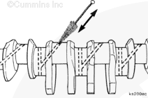
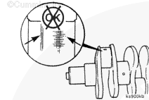
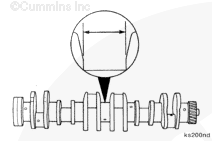
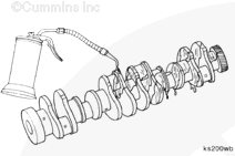
Use a micrometer to measure the connecting rod journals.
Crankshaft Connecting Rod Journal Diameter
mm
in
76.000
MIN
2.9921
76.026
MAX
2.9931
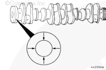
Crankshaft Connecting Rod Out of Roundness
mm
in
0.050
MAX
0.002
Crankshaft Connecting Rod Journal Taper
mm
in
0.013
MAX
0.0005
NOTE: If the crankshaft connecting rod journals are not within the given specifications, the crankshaft must be reground. Always grind all of the journals when one is not within specifications. Oversize connecting rod bearings are available; see the appropriate parts catalog.
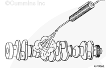
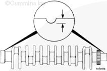
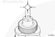
Use a micrometer to measure the crankshaft main bearing journals.
Crankshaft Main Bearing Journal Diameter
mm
in
98.006
MIN
3.8585
98.032
MAX
3.8595
Crankshaft Main Bearing Journal Out of Roundness
mm
in
0.050
MAX
0.002
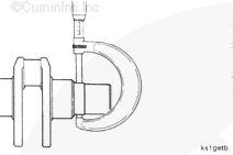
Crankshaft Main Bearing Journal Taper
mm
in
0.013
MAX
0.0005
NOTE: If the crankshaft main bearing journals are not within the given specifications, the crankshaft must be reground. Always grind all of the journals when one is not within specifications. Oversize connecting rod bearings are available; see the appropriate parts catalog.
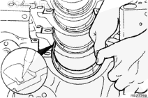
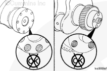
The tang (1) on the bearing shell must be in the slot (2) of the bearing saddle to correctly position the bearing and prevent engine damage.
Upper Main Bearings
Do not lubricate the side of the main bearing that is against the cylinder block.
Apply a coat of assembly lubricant, Part Number 3163087 or equivalent, to the crankshaft side of the upper main bearings.
NOTE: Make sure the main bearing being installed is the same size as the main bearing that was removed. The size is engraved on the back of the main bearing.
NOTE: The crankshaft thrust bearing must be installed in the number four position.
NOTE: The upper and lower main bearing shells of some engines are not interchangeable. The backs of the main bearings are marked with the proper orientation, if required.
NOTE: If used bearing shells are to be installed, they must be installed in their original locations, as marked during disassembly.
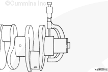
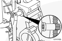
With the engine fully assembled, check to be sure the engine rotates freely. Use barring tool, Part Number 3824591.
Insert the barring tool into the flywheel housing and engage the flywheel/flexplate ring gear. The crankshaft can then be rotated by hand, using a 1/2-inch ratchet or breaker bar.
If the engine does not rotate freely, check for any external obstructions (flywheel/flexplate, engine-driven accessories, etc.). If no obstructions are found, remove the oil pan and look for internal damage.
Hello, I'm Jack, a diesel engine fan and a blogger. I write about how to fix and improve diesel engines, from cars to trucks to generators. I also review the newest models and innovations in the diesel market. If you are interested in learning more about diesel engines, check out my blog and leave your feedback.
View all posts by Jack
 WARNING


 CAUTION
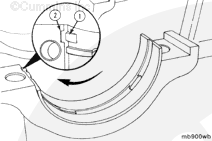

;)
;)
;)
;)
;)
;)
;)
;)
;)
;)
;)
;)
;)
;)
;)
;)
;)
;)
;)
;)
;)
;)
;)
;)
;)
;)
;)
;)
;)
;)
;)
;)