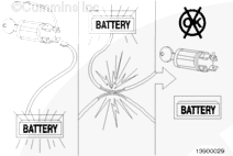
Batteries can emit explosive gases. To reduce the possibility of personal injury, always ventilate the compartment before servicing the batteries. To reduce the possibility of arcing, remove the negative (-) battery cable first and attach the negative (-) battery cable last.
WARNING
This component or assembly weighs greater than 23 kg [50 lb]. To prevent serious personal injury, be sure to have assistance or use appropriate lifting equipment to lift this component or assembly.
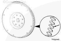
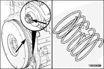
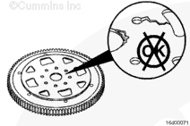
A mechanical issue can typically be identified by seeing damage to the ring gear of the flexplate in 3 distinct locations for 6 cylinder engines (commonly called 120 degree milling), and 2 locations for 4 cylinder engines (commonly called 180 degree milling). The following can be causes for mechanical issues:
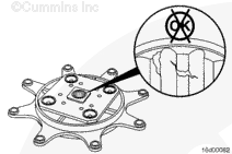
The interference between the ring gear land area and the starting motor pinion. The wrong starting motor might be installed, refer to the original equipment manufacturer’s specifications.
The possibility of a damaged starter motor pinion. Inspect the pinion for nicks and burrs. If replacement of the starting motor is necessary. Refer to Procedure 013-020 in Section 13.
The torque converter/transmission is damaged or incorrectly mounted. Refer to the OEM service manual.
Incorrect starting motor pinion to flexplate ring gear pitch and teeth match. Refer to the OEM service manual.
An electrical issue can typically be identified by seeing damage to the ring gear of the flexplate 360 degrees around the circumference of the ring gear (commonly called 360 degree milling). The following can be causes for electrical issues:
The operator is attempting to start engine while engine is already running. Check if a starter lockout feature is available through the OEM (activated with INSITE™ electronic service tool) or the starting motor manufacturer.
The orientation of the starter relay, where in the direction of the pull contact is in the direction of the vehicle’s travel. This results in intermittent starter motor engagement when the engine is running. Relocate the starter relay. Refer to the OEM service manual.
Intermittent starter motor wiring issues. Refer to the OEM service manual.
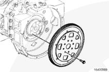
NOTE: Some flexplates require mounting plates and/or adapters. It may be necessary to remove any mounting plates and/or adapters prior to or with the flexplate. Make sure to note the location of any mounting plates and/or adapters for later installation.
NOTE: Some flexplates require mounting plates and/or clamp rings. It may be necessary to install any mounting plates and/or clamp rings prior to or with the flexplate as noted during removal.
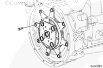
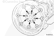
Install the flexplate, the flexplate capscrews, and tighten.
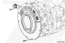
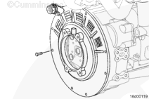
If the engine is equipped with a flex-coupling guard plate, install the flex-coupling guard plate onto the flywheel housing. Position the wiring harness connector at the 11 o’clock position, as shown in the illustration. Install a capscrew to hold it in place.
Batteries can emit explosive gases. To reduce the possibility of personal injury, always ventilate the compartment before servicing the batteries. To reduce the possibility of arcing, remove the negative (-) battery cable first and attach the negative (-) battery cable last.
WARNING
This component or assembly weighs greater than 23 kg [50 lb]. To prevent serious personal injury, be sure to have assistance or use appropriate lifting equipment to lift this component or assembly.
Hello, I'm Jack, a diesel engine fan and a blogger. I write about how to fix and improve diesel engines, from cars to trucks to generators. I also review the newest models and innovations in the diesel market. If you are interested in learning more about diesel engines, check out my blog and leave your feedback.
View all posts by Jack
 WARNING


;)
;)
;)
;)
;)
;)
;)
;)
;)
;)
;)
;)
;)
;)
;)
;)
;)
;)
;)
;)
;)
;)
;)
;)