Batteries can emit explosive gases. To reduce the possibility of personal injury, always ventilate the compartment before servicing the batteries. To reduce the possibility of arcing, remove the negative (-) battery cable first and attach the negative (-) battery cable last.
This component or assembly weighs greater than 23 kg [50 lb]. To prevent serious personal injury, be sure to have assistance or use appropriate lifting equipment to lift this component or assembly.
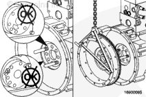
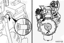
Use a hoist or suitable lifting device to support the rear of the engine if the engine supports are mounted to the marine gear.
Remove the propeller shaft, marine gear and drive plate. Refer to the vessel OEM or marine gear OEM service manual.
Remove the marine gear housing adapter, if used. Refer to the marine gear OEM service manual.
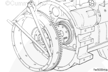
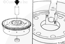
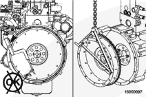
NOTE: Use the barring tool, Part Number 3824591, to hold the flywheel to prevent rotation.
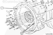
Remove two capscrews 180 degrees apart.
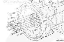
Install two M12 x 1.25 x 90-mm guide pins.
NOTE: If a clutch is used in the equipment, the threads in the clutch pressure plate mounting capscrew holes can be metric or standard. Be sure to use the correct capscrews.
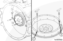
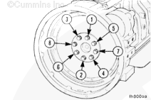
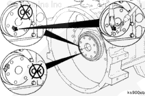
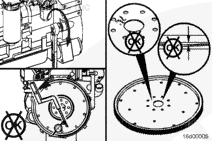
Determine the capscrew thread design and size, and install two T-handles in the flywheel at points (1) and (2).
Remove the remaining six flywheel mounting capscrews.
This component or assembly weighs greater than 23 kg [50 lb]. To prevent serious personal injury, be sure to have assistance or use appropriate lifting equipment to lift this component or assembly.
When using a steam cleaner, wear safety glasses or a face shield, as well as protective clothing. Hot steam can cause serious personal injury.
WARNING
Wear appropriate eye and face protection when using compressed air. Flying debris and dirt can cause personal injury.
WARNING
When using solvents, acids, or alkaline materials for cleaning, follow the manufacturer’s recommendations for use. Wear goggles and protective clothing to reduce the possibility of personal injury.
If the pilot bearing was removed, use a wire brush to clean the crankshaft pilot bore.
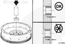
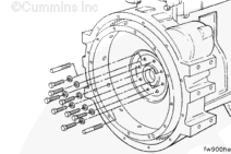
Install two M12 x 1.25 x 90-mm guide pins into the crankshaft flange 180 degrees apart.
NOTE: If a clutch is used in the equipment, the threads in the clutch pressure plate mounting capscrew holes can be metric or standard. Be sure to use the correct capscrews.
Determine the capscrew thread design and size, and install two T-handles into the flywheel at points (1) and (2).
This component or assembly weighs greater than 23 kg [50 lb]. To prevent serious personal injury, be sure to have assistance or use appropriate lifting equipment to lift this component or assembly.
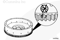
Inspect the rear face of crankshaft and flywheel mounting flange for cleanliness and nicks or burrs.
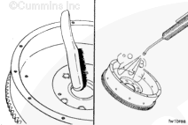
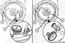
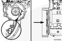
Use the dial indicator gauge (1), Part Number 3376050, or its equivalent and dial gauge attachment (2), Part Number ST-1325, to inspect the flywheel bore (3) and the surface (4) runout.
Install the attachment to the flywheel housing.
Install the gauge on the attachment.
Install the contact tip of the indicator against the inside diameter of the flywheel bore, and set the dial indicator at zero.
This component or assembly weighs greater than 23 kg [50 lb]. To prevent serious personal injury, be sure to have assistance or use appropriate lifting equipment to lift this component or assembly.
NOTE: If the total indicator reading (TIR) is greater than the specification, do the following:
This component or assembly weighs greater than 23 kg [50 lb]. To prevent serious personal injury, be sure to have assistance or use appropriate lifting equipment to lift this component or assembly.
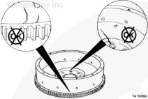
Install the contact tip of the indicator against the flywheel face.
When locating the contact tip, see the Flywheel Face Runout Total Indicator Reading Table later in this procedure. Locate the contact tip so that it corresponds with a radius listed in the table, but is still as close to the outside diameter of the flywheel as possible, to inspect the flywheel face (1) runout.
Push the flywheel forward to remove the crankshaft end clearance. Adjust the dial on the indicator until the needle points to zero.
Use the barring tool, Part Number 3824591, to rotate the crankshaft one complete revolution. Measure and record the flywheel runout at four equal points on the flywheel.
The flywheel must be pushed toward the front of the engine to remove the crankshaft end clearance each time a point is measured.
Determine the total indicator reading (TIR).
TIR is determined by calculating the difference between the highest and lowest measurement from the four locations measured.
If the flywheel face runout is not within specifications, remove the flywheel. Check for nicks, burrs, or foreign material between the flywheel mounting surface and the crankshaft flange.
Replace the flywheel if the runout is not within specification.
Batteries can emit explosive gases. To reduce the possibility of personal injury, always ventilate the compartment before servicing the batteries. To reduce the possibility of arcing, remove the negative (-) battery cable first and attach the negative (-) battery cable last.
Install the clutch discs and the pressure plate.
NOTE: Use the barring tool, Part Number 3824591, to hold the flywheel to prevent rotation.
Install the vehicle driveline and transmission. See the manufacturer’s service manual.
Hello, I'm Jack, a diesel engine fan and a blogger. I write about how to fix and improve diesel engines, from cars to trucks to generators. I also review the newest models and innovations in the diesel market. If you are interested in learning more about diesel engines, check out my blog and leave your feedback.
View all posts by Jack
 WARNING


;)
;)
;)
;)
;)
;)
;)
;)
;)
;)
;)
;)
;)
;)
;)
;)
;)
;)
;)
;)
;)
;)
;)
;)
;)
;)
;)
;)
;)
;)
;)
;)
;)
;)
;)
;)
;)
;)
;)
;)