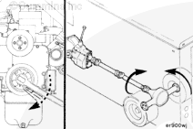
If the starting motor solenoid is making a sound but the engine is not rotating, turn the keyswitch to the OFF position, and attempt to bar the crankshaft in both directions.
Bar the engine, use the barring tool, Part Number 3824591.
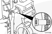
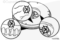
If the crankshaft will bar over, attempt to start the engine. If the starting motor cranks the engine, check the starting motor pinion gear and flywheel ring gear for damage.
If damage to the starting motor pinion gear and/or flywheel ring gear is found when replacing the components, make sure to measure the distance from the starting motor mounting flange to the forward face of the front side of the flywheel ring gear. Follow the measure step of this procedure .
If the crankshaft does not rotate or requires more than the normal effort to bar, check for an internal malfunction or a problem with the drive unit and/or accessories.
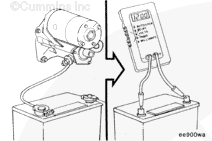
Check the voltage at the starting motor during cranking. If the voltage drops more than 2.4 VDC on a 12-VDC system, or 4.8 VDC on a 24-VDC system, check that all connections are clean and tight.
If the cables are correct and the voltage drop exceeds the limit, replace the starting motor.
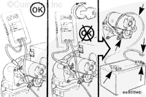
Batteries can emit explosive gases. To reduce the possibility of personal injury, always ventilate the compartment before servicing the batteries. To reduce the possibility of arcing, remove the negative (-) battery cable first and attach the negative (-) battery cable last.
WARNING
When using a steam cleaner, wear safety glasses or a face shield, as well as protective clothing. Hot steam can cause serious personal injury.
WARNING
Wear appropriate eye and face protection when using compressed air. Flying debris and dirt can cause personal injury.
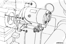
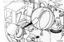
Identify each wire with a tag indicating its location on the starting motor.
Remove the electrical connections from the starting motor.
Remove the three capscrews and the starting motor.
If equipped with a System Integration Module relay, remove the relay support bracket from the starting motor mounting capscrew.
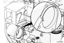
If equipped with a starting motor spacer, remove the spacer and clean all surfaces between the starting motor, starting motor spacer, and flywheel housing with a wire brush.
For engines that use wet flywheel housing, clean any left over sealant from the starting motor mounting flange on both the flywheel housing and starting motor. Make sure these surfaces are clean of oil and debris.
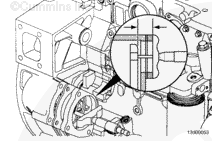
Use a depth micrometer or vernier caliper to measure the distance from the starting motor mounting flange to the forward face of the front side of the flywheel ring gear.
NOTE: Include any spacers previously removed when completing the measurement.
Starting Motor Spacing
mm
in
49.28
MIN
1.94
52.32
MAX
2.06
Add or remove spacers as necessary to achieve the correct starting motor spacing.
For engines with wet flywheel housings, apply a 1.5 to 2.0 mm [0.06 to 0.09 in] wide bead of sealant, Part Number 3164067, to the flywheel housing starting motor mounting flange.
NOTE: If a starting motor spacer is required, make sure to apply sealant to the side of the spacer that contacts the starting motor.
Batteries can emit explosive gases. To reduce the possibility of personal injury, always ventilate the compartment before servicing the batteries. To reduce the possibility of arcing, remove the negative (-) battery cable first and attach the negative (-) battery cable last.
Hello, I'm Jack, a diesel engine fan and a blogger. I write about how to fix and improve diesel engines, from cars to trucks to generators. I also review the newest models and innovations in the diesel market. If you are interested in learning more about diesel engines, check out my blog and leave your feedback.
View all posts by Jack


 WARNING


 CAUTION
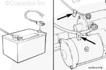

;)
;)
;)
;)
;)
;)
;)
;)
;)
;)
;)
;)
;)
;)
;)
;)
;)
;)
;)
;)
;)
;)