To reduce the possibility of personal injury, avoid direct contact of hot oil with your skin.
WARNING
Some state and local agencies have determined that used engine oil can be carcinogenic and can cause reproductive toxicity. Avoid inhalation of vapors, ingestion, and prolonged contact with used engine oil. If not reused, dispose of in accordance with local environmental regulations.
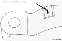
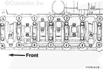
Before removing the main bearing caps, make certain that the caps are clearly marked for their location on the lubricating oil cooler side of the main bearing cap.
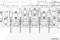
When replacing bearings in chassis, replace number 2 through number 6 while the number 1 and number 7 caps support the crankshaft. After replacing number 2 through number 6, replace number 1 and number 7.
Remove all main bearing caps except the number 1 and number 7 main bearing caps.
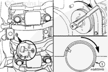
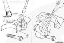
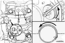
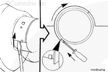
Use care so the screwdriver does not damage the crankshaft or cylinder block.
NOTE: The front main bearing, number 1, does not have a hole in the journal, so the tool can not be used to replace the bearing.
Use a flat blade screwdriver to gently bump the end of the bearing to loosen it from the cylinder block. Then, use finger pressure against the main bearing shell and rotate the crankshaft to roll the main bearing out.
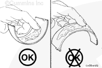
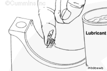
Do not lubricate the side that is against the cylinder block.
NOTE: Make sure the main bearing being installed is same size as the main bearing removed. The size is engraved on the back of the main bearing.
Apply a coat of assembly lubricant, Part Number 3163086 or equivalent, to the crankshaft side of the main bearings.
NOTE: The crankshaft thrust bearing must be installed in the number four position.
NOTE: The upper and lower main bearing shells of some engines are not interchangeable. The backs of the main bearings are marked with the proper orientation, if required.
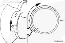
Insert the side of the main bearing opposite the tang first. Install as far as possible by hand.
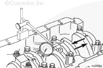
When installing the thrust bearing in the number four journal, it could be necessary to push the crankshaft to the front or rear of the cylinder block.
Make sure the pin does not slide under the bearing.
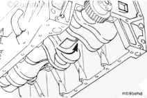
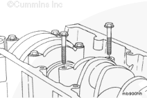
Using the main bearing replacer, Part Number 3823818, finish installing the main bearing by rotating the crankshaft. Rotate the crankshaft using the barring tool, Part Number 3824591.
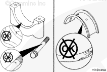
Make sure the tang (1) on the main bearing is located in the notch (2) of the cylinder block.
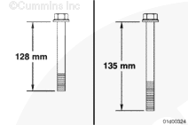
Some engines use 128 mm [5 in] long main bearing cap capscrews. Others use 135 mm [5.3 in] long main bearing cap capscrews. Failure to use the correct torque value for either size capscrew can result in engine damage.
Hello, I'm Jack, a diesel engine fan and a blogger. I write about how to fix and improve diesel engines, from cars to trucks to generators. I also review the newest models and innovations in the diesel market. If you are interested in learning more about diesel engines, check out my blog and leave your feedback.
View all posts by Jack
 WARNING


 CAUTION
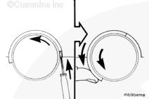


;)
;)
;)
;)
;)
;)
;)
;)
;)
;)
;)
;)
;)
;)
;)
;)
;)
;)
;)
;)
;)
;)
;)
;)
;)
;)
;)
;)
;)
;)
;)
;)
;)
;)
;)
;)