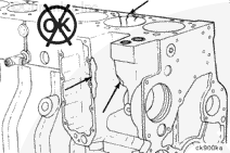
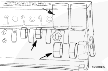
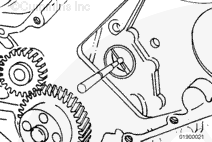
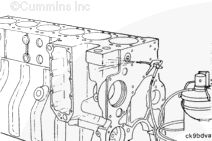
Before cleaning or further disassembly of the block, perform an inspection to see if there is any damage (cracks, fretting, etc.) that would prohibit reuse. Give special attention to areas of the block that include:
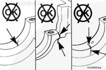
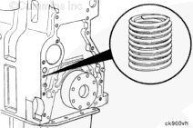
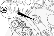
Inspect all pipe plugs, expansion plugs, and straight thread plugs for signs damage or leaks.
If it is necessary to thoroughly clean the cylinder block for reuse, remove all pipe plugs, expansion plugs, and straight thread plugs, as necessary. This will make sure all oil and coolant passages can be cleaned out.
This component or assembly weighs greater than 23 kg [50 lb]. To prevent personal injury, be sure to have assistance or use appropriate lifting equipment to lift this component or assembly.
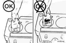
When using solvents, acids, or alkaline materials for cleaning, follow the manufacturer’s recommendations for use. Wear goggles and protective clothing to reduce the possibility of personal injury.
CAUTION
If the camshaft bushings have not been removed, make sure to use a cleaning solution that will not damage the camshaft bushing(s).
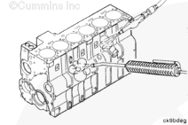
Follow the manufacturer’s operating instructions for the cleaning tank.
Follow the solvent manufacturer’s instructions for using the solvent.
NOTE: Cummins Inc. does not recommend any specific cleaning solution. Experience has shown the best results are obtained by the use of a cleaning solution that can be heated from 80 to 95°C [176 to 203°F] and a cleaning tank that will mix and filter the cleaning solution.
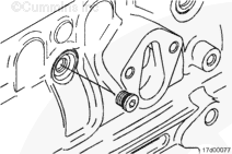
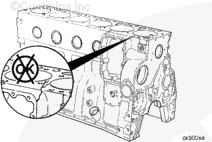
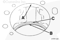
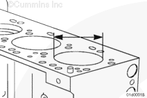
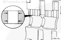
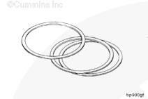
Inspect the counterbore for extreme wear or cracks.
If surface C has signs of extreme wear, the counterbore will require machining and the installation of shims for the correct liner protrusion. See the Repair section of this procedure.
All measurements of the cylinder block must be made when the cylinder block is positioned on a flat surface with the main bearing caps installed.
If the cylinder block is mounted on the engine stand and/or the main bearing caps are not installed, the measurements can be incorrect because of distortion to the cylinder bores, main bearing bores, camshaft bores, etc.
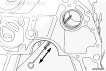
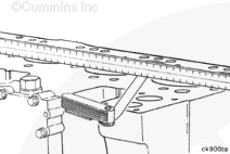
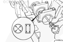
Check the cylinder block head deck for flatness between each cylinder.
Cylinder Block Flatness Specification
mm
in
0.075
End-to-end
0.003
0.075
Side-to-side
0.003
Inspect for any localized dips or imperfections. If any damage is detected, or the flatness is out of specification, the cylinder block must be replaced.
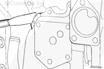
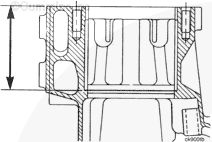
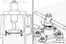
Cylinder Block Counterbore Depth from Cylinder Block Head Deck
mm
in
122.930
MIN
4.8397
123.000
MAX
4.8425
NOTE: If any of the liner counterbore depths are out of specification, the counterbore can be machined and shims installed. See the Repair section of this procedure.
If replacing the cylinder block or using a previously stored cylinder block, make sure to clean any oil/rust preventative solvent from the cylinder bores, gasket sealing areas, and main bearing bores prior to use.
Hello, I'm Jack, a diesel engine fan and a blogger. I write about how to fix and improve diesel engines, from cars to trucks to generators. I also review the newest models and innovations in the diesel market. If you are interested in learning more about diesel engines, check out my blog and leave your feedback.
View all posts by Jack


 WARNING
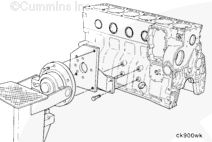
 CAUTION
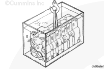


;)
;)
;)
;)
;)
;)
;)
;)
;)
;)
;)
;)
;)
;)
;)
;)
;)
;)
;)
;)
;)
;)
;)
;)
;)
;)
;)
;)
;)
;)
;)
;)
;)
;)
;)
;)
;)
;)
;)
;)
;)
;)
;)
;)
;)
;)
;)
;)