System Operation Description:
Use this procedure under the following situation:
Use this procedure to determine if the circuit for the torque limit switch is operating correctly.
The following background information is related to this procedure:
The ECM can use various inputs in a number of ways. The inputs depend on the parameter programming. Certain features are available on several different inputs. The configuration for the switch must match the actual switch installation in order for the switch to function properly.
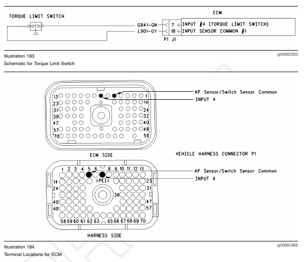
Torque Limit Switch
The torque limit switch provides a way to temporarily protect equipment from damage that is caused by applying too much torque. Torque limiting is typically used during PTO operation. Torque limiting can also be used when the PTO On/Off switch is in the OFF position.
In order to use torque limiting, a “Torque Limit” must be programmed. The “Torque Limit” parameter is located under the “Dedicated PTO Parameters”. The default setting is 3400 N·m (2500 lb ft). The “Torque Limit Switch” input selection must also be programmed. If the “Torque Limit Switch” parameter is programmed to “None” (default), this feature is not used. If the “Torque Limit Switch” is programmed to J1/P1:7, then the feature is available and the switch circuit should be connected to terminal 7 of the J1/P1 ECM vehicle harness connector.
Note: The wiring for your particular application may be slightly different. The circuits for the sensor common are used interchangeably by the OEM of the vehicle. The following circuits are common within the ECM:
• The “Input Sensor Common 1” is terminal 18.
• The “Input Sensor Common 2” is terminal 3.
• The “AP Sensor/Switch Sensor Common” is terminal 5.
Test Step 1. Check the Electrical Connectors and the Wiring
A. Thoroughly inspect the ECM vehicle harness connector J1/P1, the connectors, and the firewall bulkhead connectors. Refer to Troubleshooting, “Electrical Connectors – Inspect” for details.
B. Perform a 45 N (10 lb) pull test on each of the wires in the ECM connector that are associated with the torque limit switch circuit.
The wires are on the following terminals:
• terminal 7
• terminal 5
C. Check the ECM connector (allen head screw) for the proper torque of 6.0 N·m (55 lb in).
D. Check the harness and the wiring for abrasion and pinch points from the battery to the ECM. Then, check from the ignition key switch to the ECM.
Refer to Illustration 184 for terminal locations for the ECM.
Expected Result:
All connectors, pins, and sockets are completely coupled and/or inserted, and the harness and wiring should be free of corrosion, abrasion, or pinch points.
Results:
• OK – Proceed to Test Step 2.
• Not OK – Repair the wiring and connectors or replace the wiring or the connectors. Ensure that all of the seals are properly connected. Verify that the repair eliminates the problem. STOP.
Test Step 2. Check the Status of the Torque Limit Switch on ET
A. Connect the Caterpillar Electronic Technician (ET) to the cab data link connector.
B. Turn the ignition key switch to the ON position.
C. Operate the switch in the ON position and the OFF position.
D. View the “Torque Limit Switch” status on ET.
E. If the “Torque Limit Switch” status indicates “Not Installed”, then the “Torque Limit Switch” parameter has not been programmed.
Expected Result:
The status screen should indicate “ON” if the switch is turned on. The status screen should indicate “OFF” if the switch is off.
Results:
• OK – The switch is operating normally. Continue troubleshooting if the original condition is not resolved. STOP.
• Not OK – The ECM is not reading the “Switch Status” change. Proceed to Test Step 3.
Test Step 3. Check the Switch Circuit for the ECM
A. Turn the ignition key switch to the OFF position.
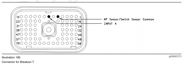
B. Install a 70 terminal breakout T to the ECM vehicle harness connector J1/P1.
C. Fabricate a jumper wire 100 mm (4 inch) long.
Crimp a Deutsch pin to both ends of the wire.
D. Insert the jumper wire into terminal 7 of the breakout T. Connect the other end of the jumper wire to terminal 5 in the breakout T. Terminal 5 is AP Sensor/Switch Common.
E. Connect ET to the cab data link connector.
F. Turn the ignition key switch to the ON position.
G. Alternately remove the jumper wire and then insert the jumper wire from terminal 5. At the same time, monitor the status screen on ET.
Expected Result:
The switch status changes to “ON” with the jumper wire in place. The switch status changes to “OFF” when the jumper wire is removed.
Results:
• OK – The ECM is functioning properly at this time. Proceed to Test Step 4.
• Not OK – The ECM is not functioning properly.
Repair: Perform the following repair:
1. Temporarily connect a test ECM.
2. Remove all jumpers and replace all connectors.
3. Recheck the system for active diagnostic codes.
4. Repeat the Test Step.
5. If the problem is resolved with the test ECM, reconnect the suspect ECM.
6. If the problem returns with the suspect ECM, replace the ECM.
7. Verify that the repair eliminates the problem.
STOP.
Test Step 4. Insert a Jumper Wire at the Switch
A. Turn the ignition key switch to the OFF position.
B. Reconnect the ECM vehicle harness connector J1/P1.
C. Fabricate a jumper wire 100 mm (4 inch) long.
Crimp a Deutsch pin to both ends of the wire.
D. Insert the jumper wire between the two switch terminals of the torque limit switch.
E. Turn the ignition key switch to the ON position.
F. Alternately remove the jumper wire and then insert the jumper wire at the switch terminals. At the same time, watch the status screen on ET.
Expected Result:
The switch status changes to “ON” with the jumper wire in place. The switch status changes to “OFF” when the jumper wire is removed.
Results:
• OK
Repair: Perform the following diagnostic
procedure:
Replace the torque limit switch.
Verify that the repair eliminates the problem.
STOP.
• Not OK – There is a problem in the wire harness between the torque limit switch and the ECM.
Proceed to Test Step 5.
Test Step 5. Insert a Jumper Wire at the Bulkhead Connector
A. Turn the ignition key switch to the OFF position.
B. Fabricate a jumper wire 100 mm (4 inch) long.
Crimp a Deutsch pin to both ends of the wire.
C. Locate the torque limit switch socket in the engine side of the ECM bulkhead connector.
D. Insert the wire jumper pin between the switch socket and the sensor common connection. Install the jumper wire on the Engine side of the ECM bulkhead connector.
E. Turn the ignition key switch to the ON position.
F. Alternately connect and then disconnect the jumper wire. At the same time, monitor the status screen on ET.
Expected Result:
The switch status changes from “ON” with the jumper wire in place. The switch status changes to “OFF” when the jumper wire is removed.
Results:
• OK – The problem is in the vehicle wiring between the Bulkhead connector and the switch. Inspect the vehicle wiring and then repair the vehicle wiring. Otherwise, send the vehicle to the OEM dealer for repair. Verify that the original condition is resolved. STOP.
• Not OK – The problem is in the vehicle wiring between the bulkhead connector and the ECM. Inspect the vehicle wiring and then repair the vehicle wiring. Otherwise, send the vehicle to the OEM dealer for repair. Verify that the original condition is resolved. STOP.