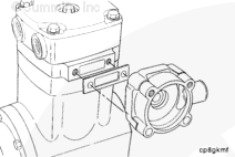
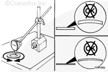
If the cylinder head is removed while the air compressor is on the engine, drain the engine coolant. Reference the specific engine application manual.
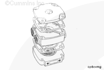
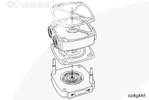
Since the valve plate, head and unloader body are indexed, marking of these parts is recommended to make sure they are reassembled in the proper orientation.
NOTE: If continuing with disassembly of the head, valve plate, and cover, make sure the work surface is clean. Debris pushed into the valve sealing surfaces by setting components on a dirty surface will cause a malfunction after assembly.
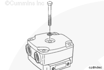
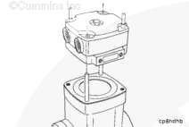
Remove the head, cover, and valve plate assembly and place it on a clean work surface with the intake valve facing upward.
When using solvents, acids, or alkaline materials for cleaning, follow the manufacturer’s recommendations for use. Wear goggles and protective clothing.
Soak the parts in a kerosene emulsion-based cleaner designed to remove carbon. The cleaner must have a pH of 9.5 or less to avoid turning aluminum parts black. The cleaner manufacturer or supplier can be contacted about solution concentration, temperature, and soak time.
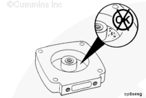
NOTE: Inspection of the valve seats in the valve plate requires specialized equipment and is beyond the scope of field service.
Inspect the valve seat surfaces.
If the valve seat is damaged, or can not be cleaned, a new valve plate is available in a service kit. Otherwise, a QE valve plate service assembly can be used.
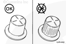
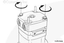
Gasket sealing surfaces must be clean and free of all old gasket material, carbon, rust, and other buildup. Surfaces must be free of scratches, gouges, burrs, and other deformities.
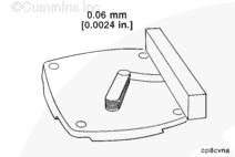
After making sure all gasket surfaces are clean and free of the above, inspect the head and cover for flatness. Use the flat plate and the feeler gauges.
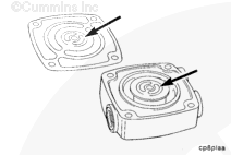
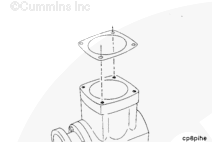
Determine the final orientation of the valve plate (air intake location) and the head (coolant ports with respect to air inlet or manifold location). Align the kidney-shaped slots in the head with the kidney shaped slots in the gasket.
If orientation marks were made before disassembly, use them.
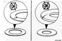
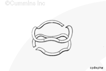
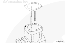
NOTE: The seal must be installed with the grooved side up.
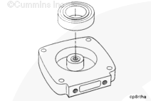
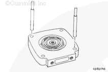
Install the new rectangular V-seal into the unloader body.
Liberally lubricate the unloader valve bore above and below the rectangular ring seal with high temperature Accrolube Lubrication Teflon grease, or equivalent.
Determine the final orientation of the valve plate (air intake location) and the head (coolant ports with respect to air inlet or manifold location). Align the kidney-shaped slots in the head with the kidney shaped slots in the gasket.
If orientation marks were made before disassembly, use them.
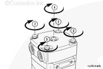
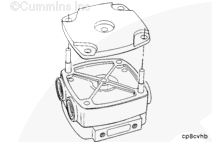
Install the head gasket onto the guide pins (either side up, but with correct slot orientation). Install the head onto the guide pins with the kidney-shaped slots aligned and toward the valve plate. Install the cover gasket over the guide pins.
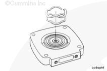
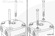
Place the remaining two guide pins in the crankcase head capscrew holes (that will not interfere with the guide pins already in the head assembly). Install the valve plate gasket.
Install the head assembly over the guide pins. Be careful not to disturb the location of the intake valve. The compressor will not work if the valve overlaps the gasket and is pinched.
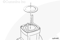
NOTE: The seal must be installed with the grooved side up.
Install the new rectangular V-seal into the unloader body.
Liberally lubricate the unloader valve bore above and below the rectangular ring seal with high temperature Accrolube Lubrication Teflon grease, or equivalent.
Hello, I'm Jack, a diesel engine fan and a blogger. I write about how to fix and improve diesel engines, from cars to trucks to generators. I also review the newest models and innovations in the diesel market. If you are interested in learning more about diesel engines, check out my blog and leave your feedback.
View all posts by Jack


 WARNING


;)
;)
;)
;)
;)
;)
;)
;)
;)
;)
;)
;)
;)
;)
;)
;)
;)
;)
;)
;)
;)
;)
;)
;)
;)
;)
;)
;)
;)
;)
;)
;)
;)
;)
;)
;)
;)
;)
;)
;)
;)
;)
;)
;)
;)
;)
;)
;)
;)
;)
;)
;)
;)
;)
;)
;)
;)
;)
;)
;)
;)
;)
;)
;)
;)
;)
;)
;)
;)
;)
;)
;)
;)
;)
;)
;)
;)
;)
;)
;)
;)
;)
;)
;)
;)
;)
;)
;)
;)
;)
;)
;)