Undersized main bearings are designed with a -0.076 mm [-0.003 in] undersized profile. These bearings were developed at a cost effective repair option to extend the life of a cylinder block that exhibits main cap fretting. The bearings increase crankshaft clearance and volume of oil flow. With the increase of oil flow, oil pressure is slightly reduced, so it recommended that only one undersized bearing kit be used per engine. Bearing shells are marked with the respective part number and are offered as a kit of one upper and lower shell. Undersized bearing shells can be identified by part number or a -0.076 mm next to the part number.
Undersized bearings have been thoroughly tested with excellent results. Bearings that have been in service for a period of time will exhibit uneven copper exposure on the lower shell. This is due to slight block bore change in geometry during fretting, with the increased oil volume of flow, undersized bearings are lubricated and cooled at a higher rate. Undersized main bearings that have been in service for a period of time will exhibit an uneven wear pattern or copper exposure. This is normal wear.
NOTE: Plastigage™ procedures will not accurately measure bearing oil film clearance in undersized main bearings.
To reduce the possibility of personal injury, avoid direct contact of hot oil with your skin.
WARNING
Some state and federal agencies have determined that used engine oil can be carcinogenic and cause reproductive toxicity. Avoid inhalation of vapors, ingestion, and prolonged contact with used engine oil. If not reused, dispose of in accordance with local environmental regulations.
Cummins Inc. recommends replacing the thrust bearings when the main bearings are replaced. Refer to Procedure 001-007 in the ISM, ISM e, and QSM11 Service Manual, Bulletin 3666322 or Procedure 001-007 in the M11 Series Engines (STC, CELECT™, CELECT™ Plus Models) Troubleshooting and Repair Manual, Bulletin 3666139 for thrust bearing replacement.
Drain the lubricating oil. Refer to Procedure 007-025.
Remove the lubricating oil pan. Refer to Procedure 007-025.
When using solvents, acids, or alkaline materials for cleaning, follow the manufacturer’s recommendations for use. Wear goggles and protective clothing to reduce the possibility of personal injury.
WARNING
Some solvents are flammable and toxic. Read the manufacturer’s instructions before using.
CAUTION
Prevent oil seepage down onto the mating faces of the block mains, cleaning of the block main capscrew threaded holes is critical. (Use cotton swabs, or equivalent, to absorb as much oil as possible prior to installing main caps.) Loctite® 518 anaerobic sealant will not seal to an oily surface.
NOTE: Loctite® 518 anaerobic sealant is available at local automotive parts stores. There is no Cummins part number available.
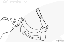
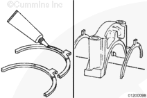
Clean the mounting surfaces of the main bearing caps with a solvent-based degreaser. Dry the mounting surfaces of the main bearing caps with a clean, lint-free cloth.
The mounting surfaces of the main bearing caps must be free of grease and oily residue.
Inspect the main cap, capscrews, and washers for damage.
Inspect the bearing shells for nicks, scratches, or damage.
If the main bearings are damaged, refer to Procedure 000-001. If the crankshaft is damaged, the engine must be removed for repair.
Refer to Procedure 000-001 in the M11 Series Engines (STC, CELECT™, CELECT™ Plus Models) Base Engine Troubleshooting and Repair Manual, Bulletin 3666139.
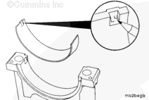
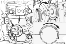
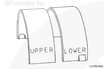
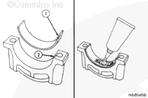
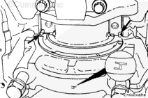
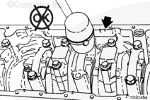
To reduce the possibility of engine damage, the upper and lower bearings must be installed in the correct location. The upper bearing has an oil groove. The bearing shells are marked with the words “upper” and “lower” for identification.
CAUTION
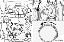
To correctly position the bearing and prevent engine damage, the bearing tang (1) must e in the slot (2) of the bearing saddle.
CAUTION
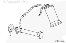
Only use Loctite® 518 anaerobic sealant on the main cap joint mating surface. Other sealants can become hard, brittle, and allow oil and debris into the main bearing/block joint.
CAUTION
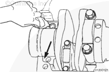
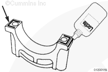
The bead must be 3 to 5 mm [0.12 to 0.2 in] wide and must not enter the main bearing shell inside diameter. Sealant in the main bearing can cause engine damage.
The bead must be 3 to 5 mm [0.12 to 0.2 in] wide and must not enter the main bearing shell inside diameter. Sealant in the main bearing can cause engine damage.
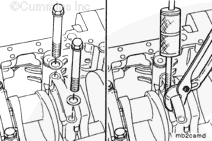
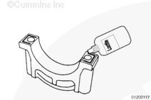
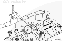
Locate the leading edge of the main bearing cap clearance chamfer.
Apply a bead of Loctite®518 anaerobic sealant to the leading edge of the main bearing cap clearance chamfer (as shown).
Repeat this procedure on the opposite side of the main bearing cap.
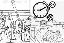
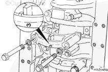
To reduce the possibility of bore size issues, clearance issues, or both, the main bearing capscrews must be tightened within 15 minutes of the Loctite® 518 anaerobic sealant application.
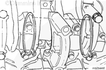
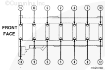
The main bearing caps are numbered 1 through 7 from front to rear in the cylinder block. The caps must be installed so the number on the cap matches the bearing saddle in the block. The lock tangs in the main bearing saddle and bearing cap must be on the same side.
Make sure the proper main cap capscrew torque procedure is used when torquing main bearings. The use of the improper torque procedure will damage the engine.
Tighten all older blocks (prior to Engine Serial Number (ESN) 35011095) main bearing capscrews in alternating sequence to the following torque values:
Torque Value:
Step 1
68 n.m [50 ft-lb]
Step 2
Loosen completely
Step 3
68 n.m [50 ft-lb]
Step 4
Rotate 180 degrees
All torque-to-yield blocks (ESN first 35011095) or blocks with TTY stamped on the rear engine serial number stamp pad must be tightened in alternating sequence to the following torque values:
Low oil pressure faults can occur if more than one set undersized main bearings are installed in the same engine.
NOTE: Both upper and lower undersized main bearing shells must be installed as a set in the same block location.
Undersized main bearing installation procedures are the same as standard main bearings procedures. Both upper and lower undersized main bearing shells must be installed as a set in the same block location.
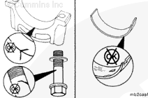
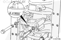
For undersized main bearing installation, mark the outside back of the main cap X -0.003 X with a permanent white Dykem® marker to identify bearing location for future repairs. Allow the Dykem® to dry before oil is added.
The engine must have adequate oil pressure within 15 seconds after starting. If the warning light indicating low oil pressure has not gone out or there is no oil pressure indicated on a gauge within 15 seconds, shut off the engine immediately to avoid engine damage. Confirm the correct oil level is in the oil pan.
Install the lubricating oil pan. Refer to Procedure 007-025.
Fill the engine with lubricating oil. Refer to Procedure 007-025.
Operate the engine to normal operating temperature and check for leaks.
Hello, I'm Jack, a diesel engine fan and a blogger. I write about how to fix and improve diesel engines, from cars to trucks to generators. I also review the newest models and innovations in the diesel market. If you are interested in learning more about diesel engines, check out my blog and leave your feedback.
View all posts by Jack

 WARNING

 CAUTION
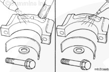


;)
;)
;)
;)
;)
;)
;)
;)
;)
;)
;)
;)
;)
;)
;)
;)
;)
;)
;)
;)
;)
;)
;)
;)
;)
;)
;)
;)
;)
;)
;)
;)
;)
;)
;)
;)
;)
;)
;)
;)
;)
;)
;)
;)
;)
;)
;)
;)
;)
;)