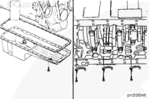
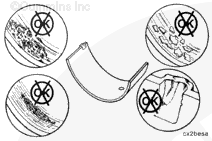
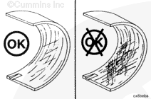
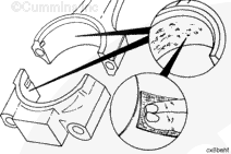
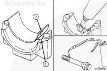
Normal bearing wear produces a smooth finish that will wear into the copper lining. Exposed copper does not always indicate worn bearings. Refer to the Parts Reuse Guidelines, Bulletin 3810303.
If large areas of copper lining are visible in the bearings before the engine has accumulated 241,000 km [150,000 mi] or 3750 hours, inspect the engine for contamination from fine dirt particles and correct the problem.
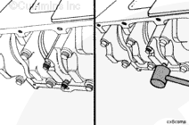
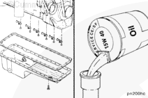
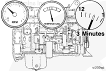
Operate the engine to normal operating temperature and check for leaks.
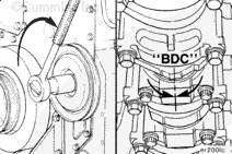
NOTE: The engine must have adequate oil pressure within 15 seconds after starting. If the warning light indicating low oil pressure has not gone out or there is no oil pressure indicated on a gauge within 15 seconds, shut off the engine immediately to avoid engine damage. Confirm the correct oil level in the oil pan.
Hello, I'm Jack, a diesel engine fan and a blogger. I write about how to fix and improve diesel engines, from cars to trucks to generators. I also review the newest models and innovations in the diesel market. If you are interested in learning more about diesel engines, check out my blog and leave your feedback.
View all posts by Jack


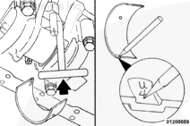
 WARNING
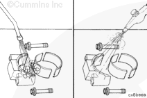


;)
;)
;)
;)
;)
;)
;)
;)
;)
;)
;)
;)
;)
;)
;)
;)
;)
;)
;)
;)
;)
;)
;)
;)
;)
;)
;)
;)
;)
;)
;)
;)
;)
;)