M11 Series – Service Manual – 001-026   Cylinder Block

View Related Topic


Basic Description

TOC

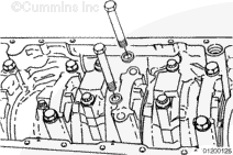
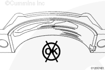
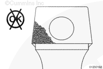
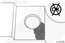
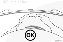
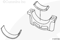
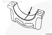
Fretting, typically occurs on main bearing caps number 2 and number 6. However, main bearing caps numbers 3, 4, and 5 are also at risk of fretting; therefore, inspection of main bearing caps number 2 through number 6 can be necessary. An inspection is conducted to determine which main bearing cap requires the Plastigage® procedure.

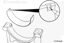
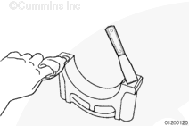
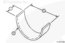
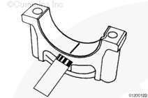
Side-to-side press fit of a main bearing cap is the fit between the block joint and the main cap sides. The intent of machining a press fit into the joint is to establish the correct position of the lower main bearing for assembly. During disassembly, it is possible to encounter a main cap with a slip fit. This is acceptable and the main cap can be reused.

Some engines have been previously inspected for main bearing cap fretting. These engines were upfitted with a stiffener plate or Service Block Kit and returned to service. These main caps must also be inspected prior to main bearing replacement or overhaul.

To determine if a stiffener plate has previously been installed, inspect the joint between the oil pan and the engine block. The stiffener plate is approximately 6.35 mm [0.25 in] thick and will be visible between the oil pan and engine block. Removal of the oil pan is not necessary to determine if a stiffener plate has been installed.

Service Block Kit incorporates the Torque-To-Yield block. These blocks were introduced into production June 28, 2000. Engine serial number (ESN) first is 35011095. These blocks require a higher main cap capscrew torque procedure than earlier production blocks.

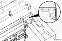
To determine if a Service Block Kit has been previously installed, inspect the engine case history. If the engine case history is not available, inspect the rear engine serial number stamp pad located on the camshaft side of the block. If the block had previously been replaced with a Torque-To-Yield Block, the letters TTY will be stamped in the rear engine serial number stamp pad.

NOTE: Do not destroy evidence-go slowly and observe all conditions.

Inspect for Reuse

TOC

 CAUTION 

Make sure the proper main cap capscrew torque procedure is used when tightening the main bearings on M11 and ISM engines. Using the incorrect torque procedure will damage the engine.
 CAUTION 

Two evenly spaced main bearing caps must be left in place to support the engine crankshaft. This prevents the crankshaft from dropping.
 CAUTION 

Do not mark the backside of the bearing shell. Marking on the backside of the bearing shell can give a false Plasitgage® reading.

SMALL | MEDIUM | LARGE


The block type must be identified to determine which main cap capscrew torque method must be used.

Torque-to-yield block

The torque-to-yield block was introduced into production June 28, 2000. ESN first is 35011095.

To determine if an older block has been replaced with a torque-to-yield block perform the following:

Review the engine case history.

Inspect the rear ESN stamp pad. A torque-to-yield service block will have the letters TTY stamped in the rear serial number stamp pad on the camshaft side of the block.

SMALL | MEDIUM | LARGE


Remove main caps 2 through 6 and arrange all parts as they are located in the engine.

Use main bearing cap puller, Part Number ST-1178, to remove the caps. The main bearing cap puller must be centered on the cap. Pull straight down to remove the cap.

Observe respective part conditions-amount and condition of lubricant present, burrs, cuts or particles in evidence, condition of journals, fillets, and so forth.

SMALL | MEDIUM | LARGE


Remove the lower main bearing shell from the cap.

Mark the bearing shell with the letter L (lower) and the journal number from which it was removed.

SMALL | MEDIUM | LARGE


Wipe oil from all main bearing cap mounting surfaces on the cylinder block with a clean, lint-free cloth.

The main bearing cap surfaces must be free of grease and oily residue to perform a proper inspection.

SMALL | MEDIUM | LARGE


Inspect the lower bearing shells for type and extent of damage, unusual wear patterns, uneven wear, or copper exposure.

An uneven wear pattern on the lower bearing shell is an indication of fretting.

If a lower bearing shell exhibits an uneven wear pattern or copper exposure, as shown here, the bearing must be Plastigaged®.

SMALL | MEDIUM | LARGE


Inspect both main cap mating surfaces for condition and unusual circumstances.

Inspect the exhaust side of the main cap and block for fretting.

Fretting appears as a frosted surface or orange peal texture on the exhaust side of the main cap.

SMALL | MEDIUM | LARGE


Inspect the block mating surfaces for condition and unusual circumstances.

Fretting appears as a frosted surface texture on the exhaust side of the block joint.

The main cap capscrew hole is larger in diameter than the mating block capscrew hole. If fretting is present, the block mating surface wears leaving the original surface material around the capscrew hole. This lip can be felt with a fingernail.

SMALL | MEDIUM | LARGE


The number 7 lower main bearing shell typically wears at the 6 o’clock position towards the rear half of the bearing surface. This wear pattern is caused by the weight of the flywheel/clutch assembly and is considered normal wear.

Inspection procedures outlined in this topic only pertain to the number 2 through 6 main bearing caps and respective lower bearing shells.

 
SMALL | MEDIUM | LARGE


Shims push the crankshaft up against the adjoining upper bearings, so an accurate clearance measurement can be made on the lower bearing.

The shims can be manufactured easily from a piece of 4-inch-diameter, schedule 40 PVC pipe. The dimensions of the fabricated shims must be as follows:

Width = 38.1 mm [1.5 in]
Thickness = 6.35 mm [0.25 in] (approximate thickness of schedule 40 PVC pipe)
Diameter = 101.6 mm [4 in].

Cut the pipe in half. The shims must be fabricated to the above-specified dimensions and be less the 180 degrees in circumference.

 
SMALL | MEDIUM | LARGE


NOTE: The PR-1 (red) style Plastigage®, clearance range of 0.05 to 0.152 mm [0.002 to 0.006 in], is required for this procedure.

To Plastigage® a main bearing journal clearance on an in-chassis engine, shims must be inserted into main caps on both sides of the journal being Plastigaged®. Shims support the crankshaft so an accurate clearance measurement can be made on the lower bearing.

SMALL | MEDIUM | LARGE


NOTE: Two fabricated shims are required for this procedure.

Remove the lower bearing shells and install the shims in the main bearing caps on both sides of the bearing being plastigaged.

For example, to check the number four main bearing cap, install the shims on the number 3 and number 5 main bearing caps. To check the number 6 main bearing cap, install the shims on the number 5 and number 7 main bearing caps.

Install the caps.

Torque Value:  34  n.m  [25 ft-lb]

SMALL | MEDIUM | LARGE


Remove the main bearing cap to be Plastigaged®.

Wipe the oil from the bearing and crankshaft journal.

Cut or tear a piece of Plastigage® as long as the full bearing width. (Tear through both the envelope and plastic thread at the same time). Open the envelope lengthwise by cutting the edge with scissors or a knife or by tearing.

NOTE: Do not squeeze the gauge material. Squeezing the gauge material can result in a false reading.

With the envelope open, lift out the Plastigage® by one end. (Roll out with the thumb if the material is stuck lightly to the paper.) Occasionally, the color in the Plastigage® material will transfer to the paper. This has no effect on accuracy.

Place the piece of Plastigage® the full length of the bearing. Insert approximately about 6 mm [0.24 in] off center. See illustration.

NOTE: The Plastigage® clearance check procedure must be performed with the original bearings. New bearings can result in a false reading.

 
SMALL | MEDIUM | LARGE


To install the main bearing cap for the M11 engines. Refer to Procedure 001-006 in the Troubleshooting and Repair Manual, M11 STC, CELECT™ and CELECT™ Plus Engines, Bulletin 3666139 or Shop Manual, M11 Series Engines, Bulletin 3666075.

To install the main bearing cap for the ISM/QSM11 engines. Refer to Procedure 001-006 in the ISM/QSM11 Troubleshooting and Repair Manual Base Engine, Bulletin 3666322.

 
SMALL | MEDIUM | LARGE


NOTE: Do not disturb the Plastigage® before reading the measurement. Disturbing the Plastigage® will result in an incorrect measurement.

Remove the main bearing cap. Compare the width of the compressed Plastigage® at its widest point, to the graduations on the envelope (regardless of taper). The number within the graduation on the envelope indicates the bearing clearance in millimeters or inches, depending on which side of the envelope is used.

Taper does not affect the clearance measurement. Clearance is still measured at the widest point on the Plastigage® strip.

 
SMALL | MEDIUM | LARGE


The only correct in-chassis method to only Plastigage® the number 7 main bearing is to insert a shim in the number 6 main cap and use a bottle jack to support the clutch/flywheel assembly (there is an access hole in the flywheel housing). This is why the number 7 main bearing is not recommended to be Plastigage® in-chassis.

 
SMALL | MEDIUM | LARGE
Last Modified:  29-Sep-2003