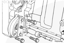
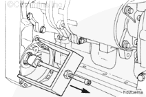
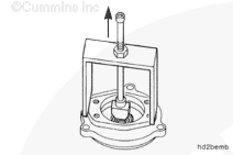
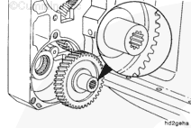
Install a slide hammer and the engine baring tool, Part Number 3824270, to the hydraulic drive adapter. Use two M10-1.50 x 30 capscrews, Part Number 3335003, for SAE A drives, or two M12-1.75 x 40 capscrews, Part Number 3018671, for SAE B drives.
When using solvents, acids, or alkaline materials for cleaning, follow the manufacturer’s recommendations for use. Wear goggles and protective clothing to reduce the possibility of personal injury.
WARNING
Wear appropriate eye and face protection when using compressed air. Flying debris and dirt can cause personal injury.
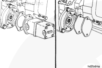
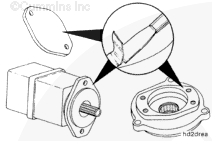
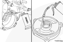
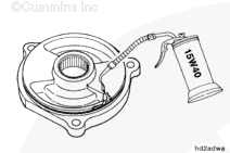
Clean the hydraulic pump adapter, cover plate, gear, and needle bearings with solvent. Dry with compressed air.
When using solvents, acids, or alkaline materials for cleaning, follow the manufacturer’s recommendations for use. Wear goggles and protective clothing to reduce the possibility of personal injury.
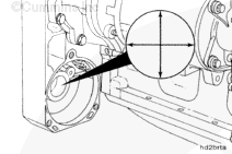
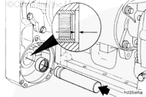
Clean the needle bearing bore in the gear housing with solvent and dry with a clean cloth.
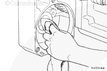
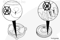
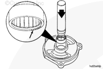
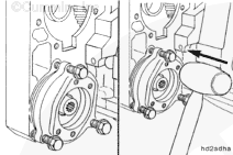
Use bearing installation tool, Part Number 3823776, included in bearing puller kit, Part Number 3823774, to install the needle bearings in the gear housing.
Tap the bearing gently until it comes in contact with the shoulder in the housing.
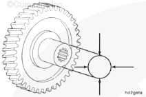
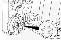
The bearing must be 0.25 to 0.76 mm [0.010 to 0.030 in] past the outside edge of the gear housing bore surface.
Hello, I'm Jack, a diesel engine fan and a blogger. I write about how to fix and improve diesel engines, from cars to trucks to generators. I also review the newest models and innovations in the diesel market. If you are interested in learning more about diesel engines, check out my blog and leave your feedback.
View all posts by Jack

 CAUTION
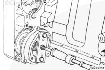

 WARNING
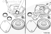


;)
;)
;)
;)
;)
;)
;)
;)
;)
;)
;)
;)
;)
;)
;)
;)
;)
;)
;)
;)
;)
;)
;)
;)
;)
;)
;)
;)
;)
;)
;)
;)
;)
;)
;)
;)
;)
;)