Remove
TOC
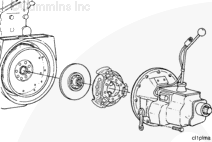
Remove the vehicle driveline and transmission. Refer to the manufacturer’s instructions.
Remove the clutch discs and pressure plate.
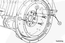
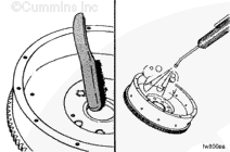
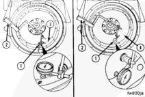
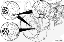
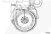
Hold the flywheel to prevent rotation.
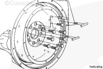
Install M10 – 1.50 x 40 puller capscrews (at points 1 and 2).
Remove capscrew (3) and install guide pin, Part No. 3376696.
NOTE : If a clutch is used in the equipment, the threads in the clutch pressure
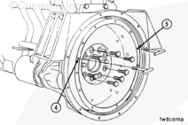
Determine the capscrew thread design and size, and install two “t-handles”
Remove the remaining seven flywheel mounting capscrews.
WARNING
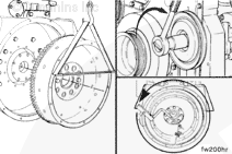
This component weighs 23 kg [50 lb] or more. To avoid personal injury, use a hoist or get assistance to lift the component.
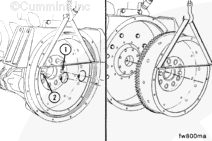
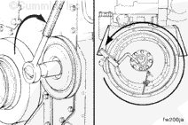
Tighten capscrews (1 and 2) in alternating sequence to loosen the flywheel.
Remove the flywheel from the guide pin.
Clean
TOC
WARNING
When using a steam cleaner, wear protective clothing, as well as safety glasses or a face shield. Hot steam can cause serious personal injury.
Use a wire brush to clean the crankshaft pilot bore.
Use steam or solvent to clean the flywheel. Dry with compressed air.
Inspect for Reuse
TOC
Inspect for nicks or burrs.
Use Scotch-Brite™ 7448, Part No. 3823258 or equivalent, to remove
WARNING
Do not use a cracked flywheel. A cracked flywheel can break and cause serious personal injury or property damage.
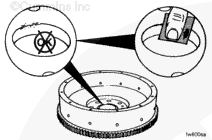
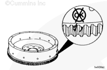
Inspect the flywheel for cracks.
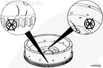
Inspect the flywheel ring gear teeth for cracks and chips.
If the ring gear teeth are cracked or broken, the ring gear
must be replaced.
Install
TOC
Use a new pilot bearing when installing a new or rebuilt clutch.
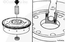
Remove the pilot bearing with a mandrel and hammer.
Clean the pilot bore with Scotch-Brite 7448, Part No. 3823258 or equivalent.
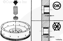
Install the pilot bearing with a mandrel and hammer.
The pilot bearing
must be installed flush with the pilot
WARNING
This component weighs 23 kg [50 lb] or more. To avoid personal injury, use a hoist or get assistance to lift the component.
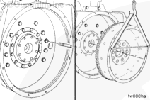
Install guide pin, Part No. 3376696, in the crankshaft flange.
Install the flywheel on the guide pin.
Install the seven capscrews.
Remove the “T-handles” and the guide pin.
Install the remaining capscrew in the hole.
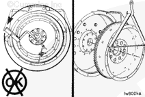
Tighten the capscrews in a star pattern.
Torque Value: 183 n.m [135 ft-lb]
Measure
TOC
Bore Runout
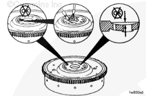
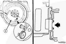
Use dial indicator gauge (1), Part No. 3376050 or equivalent, and dial
Install the attachment to the flywheel housing.
Install the gauge on the attachment.
Install the contact tip of the indicator against the inside diameter
Use the accessory driveshaft to rotate the crankshaft one complete
The total indicator reading
must not exceed 0.127 mm [0.0050 in].
WARNING
This component weighs 23 kg [50 lb] or more. To avoid personal injury, use a hoist or get assistance to lift the component.
If the total indicator reading is greater than the specification:
Inspect the flywheel mounting surface for dirt or damage.
WARNING
This component weighs 23 kg [50 lb] or more. To avoid personal injury, use a hoist or get assistance to lift the component.
Install the flywheel, and inspect the bore runout again.
WARNING
This component weighs 23 kg [50 lb] or more. To avoid personal injury, use a hoist or get assistance to lift the component.
Replace the flywheel if the runout does
not meet specifications.
Face Runout
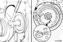
Install the contact tip of the indicator against the flywheel face as
Push the flywheel forward to remove the crankshaft end thrust.
Use the accessory driveshaft to rotate the crankshaft one complete
The total indicator reading
must not exceed the following specifications.
Flywheel Face Runout Total Indicator Reading
Flywheel Radius
Maximum Total Indicator Reading of
mm in mm in
203
8
0.203
0.008
254
10
0.254
0.010
305
12
0.305
0.012
356
14
0.356
0.014
406
16
0.406
0.016
Install the clutch discs, pressure plate, transmission, and driveline, if equipped, in reverse order of removal. Refer to the manufacturer’s instructions.
Align the universal joints on each end of the driveshaft to prevent vibration.
Last Modified: 07-May-2003
Published by Jack
Hello, I'm Jack, a diesel engine fan and a blogger. I write about how to fix and improve diesel engines, from cars to trucks to generators. I also review the newest models and innovations in the diesel market. If you are interested in learning more about diesel engines, check out my blog and leave your feedback.
View all posts by Jack


 WARNING


;)
;)
;)
;)
;)
;)
;)
;)
;)
;)
;)
;)
;)
;)
;)
;)
;)
;)
;)
;)
;)
;)
;)
;)
;)
;)
;)
;)
;)
;)
;)
;)
;)
;)
;)
;)
;)
;)
;)
;)
;)
;)