B5.9G, B5.9LPG – Troubleshooting and Repair Manual – 001-025   Crankshaft Wear Sleeve, Front

Preparatory Steps

TOC

Remove the drive belt. Refer to Procedure 008-002.

SMALL | MEDIUM | LARGE


Remove the vibration damper. Refer to Procedure 001-052.

SMALL | MEDIUM | LARGE
   

Remove

TOC

Remove the gear cover. Refer to Procedure 001-031.

SMALL | MEDIUM | LARGE


 CAUTION 

Do not nick or gouge the crankshaft with the chisel. If the crankshaft is damaged, it must be be replaced.

NOTE: Use a hammer and chisel that is only as wide as the wear sleeve.

Make one or two chisel marks across the wear sleeve. This will expand the wear sleeve, allowing the sleeve to be removed.

SMALL | MEDIUM | LARGE
   

Clean

TOC

Use a crocus cloth to remove any rust or other deposits from the crankshaft flange.

Use a clean cloth to clean the crankshaft flange.

SMALL | MEDIUM | LARGE
   

Inspect for Reuse

TOC

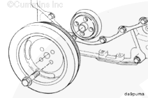
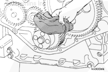
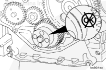
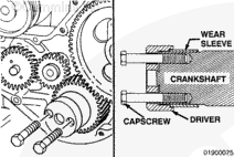
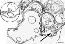
Inspect the seal contact area of the crankshaft for a wear groove. If the seal has worn a groove deep enough to be felt with a sharp object or fingernail, it will be necessary to install a wear sleeve to prevent an oil leak.

The oil seal used with the wear sleeve has a larger inside diameter than the standard seal. The two seals are not interchangeable. Refer to the appropriate B Series parts catalog for the correct part number.

SMALL | MEDIUM | LARGE
   

Install

TOC

Crankshaft Front Wear Sleeve Installation Tool, Part No. 3824500

Use the driver to install the wear sleeve to the correct position on the crankshaft. The kit consists of the following:

1 Driver 1
2 Spacer 2
3 Capscrew M14 x 1.5 x 60 mm 2
4 Hairpin Cotter 2

SMALL | MEDIUM | LARGE


Apply a thin coat of clean lubricating engine oil to the inside diameter and capscrew threads.

SMALL | MEDIUM | LARGE


Apply a thin coat of clean lubricating engine oil to the crankshaft flange.

Position the chamfered end of the wear sleeve onto the end of the crankshaft.

SMALL | MEDIUM | LARGE


Position the counterbore end of the driver onto the wear sleeve.

SMALL | MEDIUM | LARGE


Install two capscrews (without spacers or hairpin cotters) through the driver and into the crankshaft capscrew holes.

Align the wear sleeve and driver perpendicular to the crankshaft.

Tighten the capscrews “finger-tight”.

SMALL | MEDIUM | LARGE


 CAUTION 

To prevent damage to the wear sleeve, do not exceed one-half revolution of each capscrew.

Alternately tighten the capscrews one-half turn until the sleeve is installed to a depth of approximately 16 mm [0.625 in].

Torque Value:  20  n.m  [15 ft-lb]

SMALL | MEDIUM | LARGE


Remove the two capscrews.

Install the spacer on each capscrew.

Install the two capscrews.

SMALL | MEDIUM | LARGE


Continue to tighten the capscrews alternately until the bottom of the driver contacts the end of the crankshaft.

SMALL | MEDIUM | LARGE


Remove the driver. Use the hairpin cotters to secure the capscrews and spacers to the tool during storage.

SMALL | MEDIUM | LARGE


Install a new seal into the gear cover. Refer to Procedure 001-023.

Install the front gear cover. Refer to Procedure 001-031.

SMALL | MEDIUM | LARGE
Last Modified:  27-Jun-2002