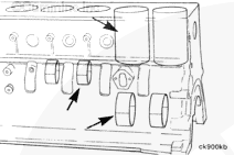
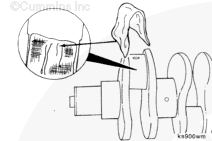
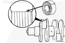
Diagnosis of cylinder block cooling and lubrication malfunctions has been discussed in those respective sections. The potential problems with the cylinder, the camshaft bore, and the crankshaft main journals have also been discussed in this section.
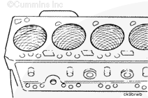
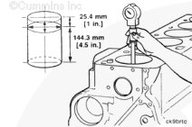
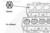
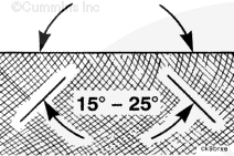
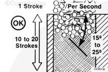
The cylinder bores are machined directly into the cylinder block during production. The size and condition of the cylinder bore are critical to engine performance and life. During repair, be sure to inspect the cylinder bore carefully. It will also be necessary to deglaze the cylinder walls before reassembly. A 30-degree crosshatch pattern is needed to seat the new piston rings.
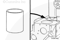
The cylinder bores can be bored in a machine shop and fitted with an oversize service piston. The cylinder bore can also be bored to accept a service sleeve and standard pistons. Refer to the B Series Alternative Repair Manual, Bulletin 3666109, for boring procedures.
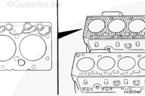
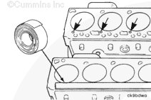
NOTE: The head surface of the block is also critical to sealing the cylinders. Inspect the surface carefully during repair before assembly. The cylinder head deck can be resurfaced in a machine shop and a thicker surface cylinder head gasket installed to keep the piston-to-head clearance the same.
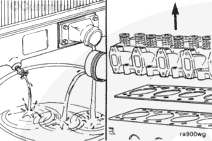
Coolant is toxic. Keep away from children and pets. If not reused, dispose of in accordance with local environmental regulations.
WARNING
Do not remove the pressure cap from a hot engine. Wait until the coolant temperature is below 50°C [120°F] before removing the pressure cap. Heated coolant spray or steam can cause personal injury.
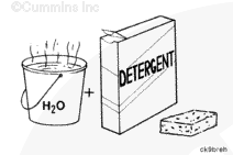
When using solvents, acids, or alkaline materials for cleaning, follow the manufacturer’s recommendations for use. Wear goggles and protective clothing to reduce the possibility of personal injury.
WARNING
Wear appropriate eye and face protection when using compressed air. Flying debris and dirt can cause personal injury.
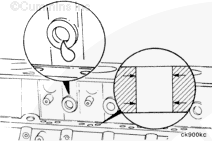
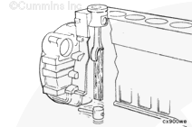
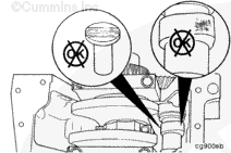
NOTE: Be sure to remove the tape covering the tappet and lubricating oil holes after the cleaning process is complete.
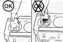
Check the cylinder bore cleanliness by wiping with a white, lint-free, lightly oiled cloth. If grit residue is still present, repeat the cleaning process until all residue is removed.
When using solvents, acids, or alkaline materials for cleaning, follow the manufacturer’s recommendations for use. Wear goggles and protective clothing to reduce the possibility of personal injury.
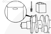
Use a solvent and a brush to clean any residue that possibly has splashed on the camshaft.
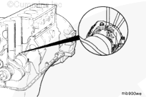
Inspect the camshaft lobes and tappet faces for signs of wear or damage. Refer to Procedure 001-008.
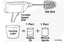
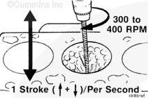
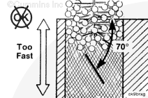
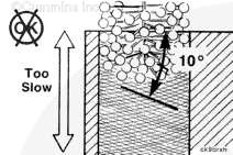
Use a drill, a fine grit flex-hone, and a mixture of equal parts of mineral spirits and SAE 10W-30 engine lubricating oil to deglaze the cylinder bores.
Hello, I'm Jack, a diesel engine fan and a blogger. I write about how to fix and improve diesel engines, from cars to trucks to generators. I also review the newest models and innovations in the diesel market. If you are interested in learning more about diesel engines, check out my blog and leave your feedback.
View all posts by Jack


 WARNING

 CAUTION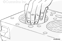




;)
;)
;)
;)
;)
;)
;)
;)
;)
;)
;)
;)
;)
;)
;)
;)
;)
;)
;)
;)
;)
;)
;)
;)
;)
;)
;)
;)
;)
;)
;)
;)
;)
;)
;)
;)
;)
;)
;)
;)
;)
;)
;)
;)
;)
;)
;)
;)
;)
;)
;)
;)
;)
;)
;)
;)
;)
;)
;)
;)