B5.9G, B5.9LPG – Troubleshooting and Repair Manual – 007-031   Lubricating Oil Pump

Preparatory Steps

TOC

  • Remove the drive belt. Refer to Procedure 008-002.

NOTE: Removal is easier if the vibration damper is loosened before removing the belt. Refer to Procedure 001-052.

SMALL | MEDIUM | LARGE

Remove

TOC

15 mm

Remove the vibration damper. Refer to Procedure 001-052.

SMALL | MEDIUM | LARGE


10 mm

Remove the front cover. Refer to Procedure 001-031.

SMALL | MEDIUM | LARGE


13 mm

Remove the four mounting capscrews.

Remove the pump from the bore in the cylinder block.

SMALL | MEDIUM | LARGE
   

Inspect for Reuse

TOC

If the lubricating oil pump is to be inspected for reuse, follow these steps.

Inspect the lubricating oil pump gears for chips, cracks, or excessive wear.

SMALL | MEDIUM | LARGE


Remove the back plate.

SMALL | MEDIUM | LARGE


Mark “TOP” on the gerotor planetary.

 
SMALL | MEDIUM | LARGE


Remove the gerotor planetary.

Inspect for excessive wear or damage.

SMALL | MEDIUM | LARGE


 WARNING 

When using solvents, acids, or alkaline materials for cleaning, follow the manufacturer’s recommendation for use. Wear goggles and protective clothing to avoid personal injury.
 WARNING 

Wear appropriate eye and face protection when using compressed air. Flying debris and dirt can cause bodily injury.

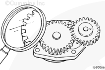
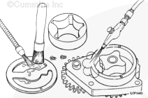
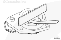
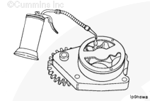
Clean all parts in solvent, and dry with compressed air.

SMALL | MEDIUM | LARGE


Inspect the lubricating oil pump housing and gerotor drive for damage and excessive wear.

SMALL | MEDIUM | LARGE


 CAUTION 

Be sure the gerotor planetary is installed in the original position. Failure to do so can cause engine damage.

Install the gerotor planetary.

SMALL | MEDIUM | LARGE


Measure the tip clearance.

Limit
mm in
0.1778 MAX 0.007

SMALL | MEDIUM | LARGE


Measure the clearance of the gerotor drive/gerotor planetary to port plate.

Limit
mm in
0.127 MAX 0.005

SMALL | MEDIUM | LARGE


Measure the clearance of the gerotor planetary to the body bore.

Limit
mm in
0.381 MAX 0.015

SMALL | MEDIUM | LARGE


Measure the gears backlash.

Limits (Used Pump)
mm in
0.076 MIN 0.003
0.330 MAX 0.013

SMALL | MEDIUM | LARGE
   

Measure

TOC

Measure the tip clearance.

Maximum Tip Clearance
mm in
0.1778 MAX 0.007

SMALL | MEDIUM | LARGE


Measure the clearance of the gerotor drive/gerotor planetary to port plate.

Gerotor Drive/Planetary to Port Plate Clearance
mm in
0.127 MAX 0.005

SMALL | MEDIUM | LARGE


Measure the clearance of the gerotor planetary to the body bore.

Gerotor Planetary to Body Bore Clearance
mm in
0.381 MAX 0.015

SMALL | MEDIUM | LARGE


Measure the gears backlash.

Gear Backlash
mm in
0.076 MIN 0.003
0.330 MAX 0.013

SMALL | MEDIUM | LARGE
   

Install

TOC

Install the back plate.

SMALL | MEDIUM | LARGE


 CAUTION 

Failure to fill the pump with oil during installation can result in a slow prime at initial engine start-up, resulting in severe engine damage.

Lubricate the lubricating oil pump with clean lubricating engine oil.

SMALL | MEDIUM | LARGE


 CAUTION 

Make sure the idler gear pin is installed in the locating bore in the cylinder block. Failure to do so can cause engine damage.

Install the lubricating oil pump.

SMALL | MEDIUM | LARGE


13 mm

Tighten in the sequence shown.

Torque Value:  24  n.m  [18 ft-lb]

SMALL | MEDIUM | LARGE


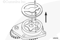
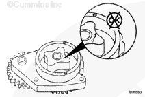
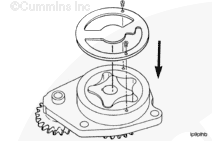
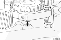
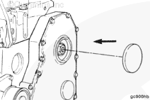
NOTE: The back plate on the pump seats against the bottom of the bore in the cylinder block. When the lubricating oil pump is correctly installed, the flange on the lubricating oil pump will not touch the cylinder block.

 
SMALL | MEDIUM | LARGE


NOTE: Be sure the gear backlash is correct if installing a new lubricating oil pump.

Measure the gear backlash.

Backlash Limits
mm in
A 0.076 MIN 0.003
  0.330 MAX 0.013
B 0.076 MIN 0.003
  0.330 MAX 0.013

NOTE: If the adjoining gear moves when you measure the backlash, the reading will be incorrect.

SMALL | MEDIUM | LARGE


Gear Cover – Installation

Lubricate the front gear train with clean lubricating engine oil.

SMALL | MEDIUM | LARGE


 CAUTION 

The seal lip and the sealing surface on the crankshaft must be free from all oil residue to prevent seal leaks.

Thoroughly clean the front seal area of the crankshaft.

NOTEAlways replace the front seal when removing and installing the gear cover.

SMALL | MEDIUM | LARGE


10 mm

Three-Bond™ Sealant, Part No. 3823494

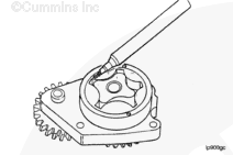
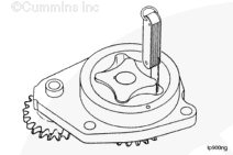
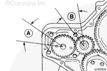
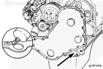
Apply a thin bead of Three-Bond™ sealant, Part No. 3823494,or equivalent, to the front cover side of the gasket only.

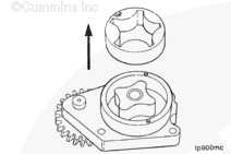
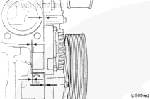
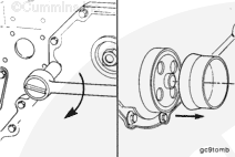
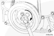
NOTE: Do not remove the plastic seal pilot tool from the lubricating oil seal at this time. Use the plastic seal pilot tool to guide the seal on the crankshaft.

Install the gasket and front cover on the engine.

SMALL | MEDIUM | LARGE


Tighten the front cover mounting capscrews.

Remove the plastic pilot tool from the crankshaft.

Torque Value:  24  n.m  [18 ft-lb]

SMALL | MEDIUM | LARGE


Install the front cover access cap and seal.

SMALL | MEDIUM | LARGE


15 mm

Install the crankshaft pulley or vibration damper. Do not
tighten the capscrews to the correct torque value at this time.

Refer to Procedure 001-052.

SMALL | MEDIUM | LARGE


1/2-Inch Square Drive

Raise the belt tensioner to install the belt.

Refer to Procedure 008-087.

SMALL | MEDIUM | LARGE


15 mm

Tighten the vibration damper.

Refer to Procedure 001-052.

Torque Value:  125  n.m  [92 ft-lb]

SMALL | MEDIUM | LARGE
Last Modified:  27-Jun-2002