When using a steam cleaner, wear protective clothing, as well as safety glasses or a face shield. Hot steam can cause serious personal injury.
WARNING
When using solvents, acids, or alkaline materials for cleaning, follow the manufacturer’s recommendations for use. Wear goggles, as well as protective clothing, to avoid personal injury.
WARNING
Compressed air used for cleaning should not exceed 207 kPa [30 psi]. Use only with protective clothing, as well as goggles/shield, and gloves to avoid personal injury.
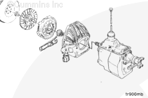
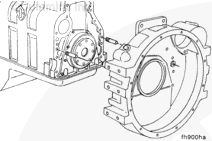
Use steam or solvent to clean the flywheel housing.
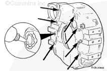
Inspect for damaged threads commonly caused by cross-threaded capscrews or installing an incorrect capscrew. Helicoils are available to repair damaged threads.
When using a steam cleaner, wear safety glasses or a face shield, as well as protective clothing. Hot steam can cause serious personal injury.
WARNING
When using solvents, acids, or alkaline materials for cleaning, follow the manufacturer’s recommendations for use. Wear goggles and protective clothing to avoid personal injury.
Thoroughly clean the flywheel housing and cylinder block mating surfaces. These surfaces must be clean of oil and debris.
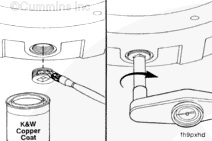
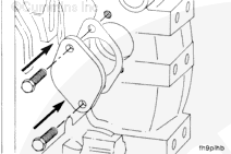
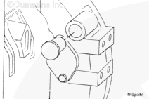
NOTE: The capscrew holes on the mounting pads are drilled through. Coat set screws with Loctite 277 and install into holes.
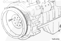
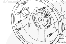
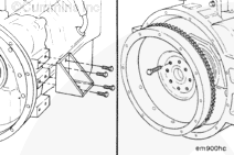
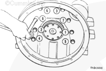
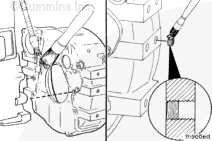
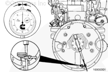
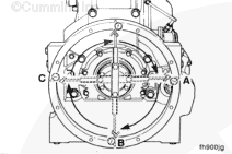
Attach the dial indicator gauge, Part No. 3376050, to the crankshaft. The dial indicator can be mounted by any method that holds the extension bar of the indicator rigid, so it does not sag. If the bar sags or the indicator slips, the readings obtained will not be accurate.
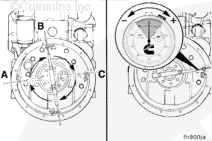
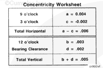
Position the indicator in the six-o’clock position, and zero the gauge.
Slowly rotate the crankshaft. Record the readings obtained at the nine-o’clock, twelve-o’clock, and three-o’clock positions as [a], [b], and [c] in the concentricity work sheet. Recheck zero at the six-o’clock position.
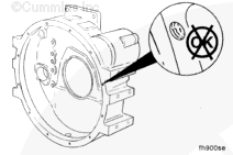
The values for (a), (b), and (c) could be positive or negative. Refer to the accompanying figure to determine the correct sign when recording these values.
Do not force the crankshaft beyond the point where the bearing clearance has been removed. Do not pry against the flywheel housing. These actions could cause false bearing clearance readings.
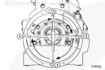
Rotate the crankshaft until the dial indicator is at the twelve o’clock position and zero the gauge.
Using a pry bar, raise the rear of the crankshaft to its upper limit. Record the value as (d) in the concentricity work sheet. This is the vertical bearing clearance adjustment and will always be positive.
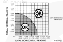
Mark the total horizontal value on the horizontal side of the chart and the total vertical on the vertical side of the chart.
Using a straightedge, find the intersection point of the total horizontal and total vertical values. The intersection point must fall within the shaded area for the flywheel housing concentricity to be within specification.
Using the total horizontal and total vertical values from the previous example, the intersection point falls within the shaded area. Therefore, the flywheel housing concentricity is within specification.
If the intersection point falls outside the shaded area, the ring dowels must be removed and the housing repositioned.
NOTE: The ring dowels are not required to maintain concentricity of the housing; the clamping force of the capscrews holds the housing in place.
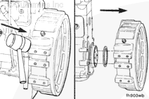
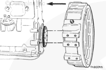
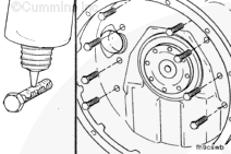
After the ring dowels are discarded, install the flywheel housing on the engine.
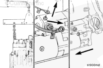
To position the housing, tighten the capscrews enough to hold the flywheel housing in place, but loose enough to allow small movement when struck lightly with a mallet.
Recheck the concentricity. When concentricity is within specification, tighten the capscrews to the specified torque value.
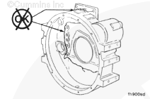
The dial indicator tip must not enter the capscrew holes, or the gauge will be damaged.
Face Alignment
Dial Indicator Gauge, Part No. 3376050
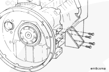
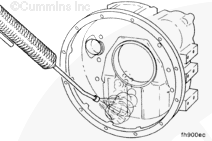
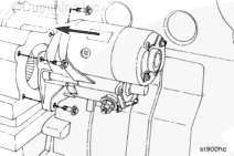
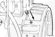
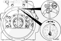
Install the dial indicator gauge, Part No. 3376050, as illustrated.
NOTE: The extension bar for the indicator must be rigid for an accurate reading. It must not sag. Position the indicator at the twelve-o’clock position. Adjust the dial until the needle points to zero.
Continue to rotate the crankshaft until the indicator is at the twelve-o’clock position. Check the indicator to make sure the needle points to zero. If it does not, the readings will be incorrect.
Hello, I'm Jack, a diesel engine fan and a blogger. I write about how to fix and improve diesel engines, from cars to trucks to generators. I also review the newest models and innovations in the diesel market. If you are interested in learning more about diesel engines, check out my blog and leave your feedback.
View all posts by Jack


 WARNING


 CAUTION
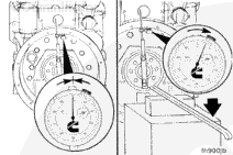
;)
;)
;)
;)
;)
;)
;)
;)
;)
;)
;)
;)
;)
;)
;)
;)
;)
;)
;)
;)
;)
;)
;)
;)
;)
;)
;)
;)
;)
;)
;)
;)
;)
;)
;)
;)
;)
;)
;)
;)
;)
;)
;)
;)
;)
;)
;)
;)
;)
;)
;)
;)
;)
;)
;)
;)
;)
;)
;)
;)
;)
;)