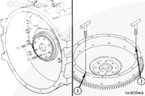
NOTE: If a clutch is used in the equipment, the threads in the clutch pressure plate mounting capscrew holes can be metric or standard. Be sure to use the correct capscrews.
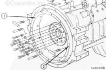
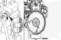
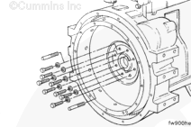
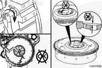
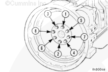
Determine the capscrew thread design and size, and install two t-handles in the flywheel at points (1 and 2).
Remove the remaining six flywheel mounting capscrews.
When using a steam cleaner, wear safety glasses or a face shield, as well as protective clothing. Hot steam can cause serious personal injury.
WARNING
When using solvents, acids, or alkaline materials for cleaning, follow the manufacturer’s recommendations for use. Wear goggles and protective clothing to avoid personal injury.
WARNING
Compressed air used for cleaning should not exceed 207 kPa [30 psi]. Wear appropriate eye and face protection when using compressed air. Flying debris and dirt can cause bodily injury.
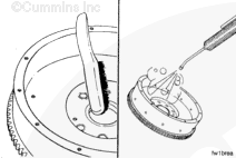
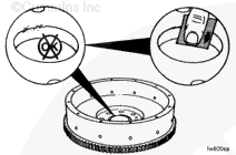
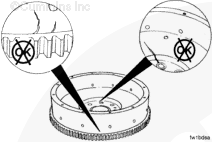
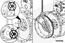
Use a wire brush to clean the crankshaft pilot bore.
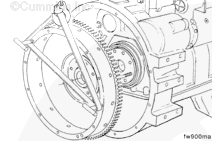
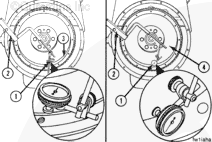
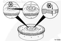
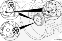
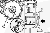
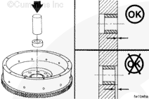
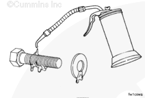
Use the dial indicator gauge (1), Part No. 3376050, or its equivalent, and dial gauge attachment (2), Part No. ST-1325, to inspect the flywheel bore (3) and the surface (4) runout.
Install the attachment to the flywheel housing.
Install the gauge on the attachment.
Install the contact tip of the indicator against the inside diameter of the flywheel bore, and set the dial indicator at zero.
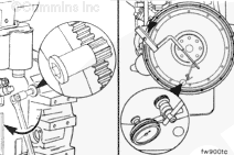
Use the barring tool, Part No. 3824591, to rotate the crankshaft one complete revolution. Measure the flywheel runout at four equal points on the flywheel.
NOTE: The flywheel must be pushed toward the front of the engine to remove the crankshaft end clearance each time a point is measured.
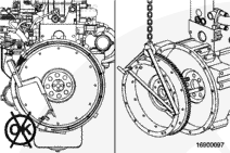
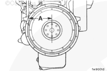
If the flywheel face runout is not within specifications, remove the flywheel. Check for nicks, burrs, or foreign material between the flywheel mounting surface and the crankshaft flange.
Install the clutch discs, pressure plate, transmission, and driveline (if equipped) in reverse order of removal. Refer to the manufacturer’s instructions.
NOTE: Align the universal joints on each end of the driveshaft to prevent vibration.
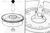
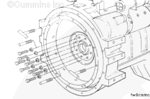
Install two M12 x 1.25 x 90-mm guide pins into the crankshaft flange 180 degrees apart.
NOTE: If a clutch is used in the equipment, the threads in the clutch pressure plate mounting capscrew holes can be metric or standard. Be sure to use the correct capscrews.
Determine the capscrew thread design and size, and install two t-handles into the flywheel (at points 1 and 2).
Hello, I'm Jack, a diesel engine fan and a blogger. I write about how to fix and improve diesel engines, from cars to trucks to generators. I also review the newest models and innovations in the diesel market. If you are interested in learning more about diesel engines, check out my blog and leave your feedback.
View all posts by Jack


 WARNING


;)
;)
;)
;)
;)
;)
;)
;)
;)
;)
;)
;)
;)
;)
;)
;)
;)
;)
;)
;)
;)
;)
;)
;)
;)
;)
;)
;)
;)
;)
;)
;)
;)
;)
;)
;)
;)
;)
;)
;)
;)
;)
;)
;)
;)
;)
;)
;)
;)
;)