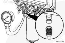
Monitor the rail fuel pressure, use INSITE™ electronic service tool or connect a pressure gauge, Part Number 3824877, on the Compuchek™ fitting (as shown), and read the rail fuel pressure.
The rail pressure while cranking at 130 rpm for at least 10 seconds is 689 kPa [100 psi]. Make sure the fuel system is primed for at least 30 seconds.
The rail fuel pressure with EGR must be 1585 to 1889 kPa [230 to 274 psi] at engine idle.
The rail fuel pressure with EGR must be 1896 to 2068 kPa [275 to 300 psi] at 2100 rpm.
The rail fuel pressure without EGR must be 1551 to 1889 kPa [225 to 274 psi] at engine idle.
The rail fuel pressure without EGR must be 1758 to 1999 kPa [255 to 290 psi] at 2100 rpm.
If the rail fuel pressure is below 689 kPa [100 psi], check to make sure there is fuel supply to the pump and that it is not restricted.
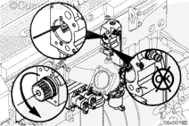
Clean the area surrounding the fuel pump. Run the engine at idle rpm.
Inspect for fuel leakage at the electronic control module (ECM) cooling plate supply and return lines and fittings. If a leak is detected, stop the test immediately and replace the damaged o-ring(s) or ECM cooling plate supply or return line(s).
Inspect for fuel or oil leakage at the fuel pump weep hole and ingetgrated fuel system module (IFSM). If leaks are detected at the fuel pump weep hole or IFSM, stop the test immediately and replace the failed component.
Inspect for fuel or oil leakage at the fuel pump mounting gasket and o-rings. If leaks are detected in these areas, stop the test immediately and replace the damaged component.
Batteries can emit explosive gases. To reduce the possibility of personal injury, always ventilate the compartment before servicing the batteries. To reduce the possibility of arcing, remove the negative (-) battery cable first and attach the negative (-) battery cable last.
Batteries can emit explosive gases. To reduce the possibility of personal injury, always ventilate the compartment before servicing the batteries. To reduce the possibility of arcing, remove the negative (-) battery cable first and attach the negative (-) battery cable last.
To perform the priming procedure, use the following items to fabricate a fuel bypass hose:
2 – Quick-disconnect fittings, Part Number 3376859
A length of clear tubing capable of 2758 kPa [ 400 psi]
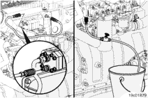
Install the fuel bypass hose fabricated above between the suction-side Compuchek™ fitting at the top of the IFSM and the fuel pump Compuchek™ fitting located on the head of the fuel pump.
Connect the clear hose and shutoff valve normally used to check for air in fuel to the rail Compuchek™ fitting. Refer to Procedure 006-003 in Section 6. Place the open end in a suitable container and fully open the shutoff valve in the hose.
Fill the fuel filter by turning the ignition keyswitch to the ON position, but do not start the engine. The fuel lift pump should begin operating. Monitor the open end of the bleed line from the rail Compuchek™ fitting. When fuel comes out the end of this line, turn the ignition switch OFF. Remove the bleed line and air in fuel test line.
NOTE: It is possible the engine will operate rough for several minutes, until all the air is out of the fuel system.
Fill the fuel filter by turning the ignition keyswitch to the ON position. The priming pump will operate for 2 minutes, which will adequately fill the fuel filter. The engine can then be started.
Some engines utilize a manual, remote mount priming pump. Flip the priming pump mounted toggle switch to the ON position. Operate the pump for 2 minutes and then turn it OFF. The engine can then be started.
Crank the engine until fuel begins to flow from the top plug. Tighten the plug.
Crank the engine for 20 seconds. If the engine does not start within 20 seconds, wait 2 minutes. If necessary, repeat these steps until the engine starts.
It is possible the engine will operate rough for several minutes, until all the air is out of the fuel system.
Hello, I'm Jack, a diesel engine fan and a blogger. I write about how to fix and improve diesel engines, from cars to trucks to generators. I also review the newest models and innovations in the diesel market. If you are interested in learning more about diesel engines, check out my blog and leave your feedback.
View all posts by Jack




 WARNING






 CAUTION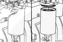


;)
;)
;)
;)
;)
;)
;)
;)
;)
;)
;)
;)
;)
;)
;)
;)
;)
;)
;)
;)
;)
;)
;)
;)
;)
;)
;)
;)
;)
;)
;)
;)
;)
;)