Do not use probes or leads other than Part No. 3822758. The OEM connector will be damaged. The leads must fit tightly in the connector without expanding the pins in the connector.
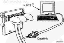
If INSITE™ is available, monitor the accelerator position sensor circuit for proper operation. If
not, follow the troubleshooting procedures in this section.
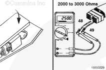
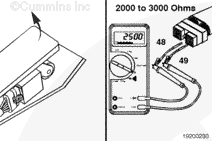
Disconnect the OEM harness connector from the ECM. Make sure the sensor is connected to the OEM harness. Insert a test lead into pin 48 (accelerator position (+) 5-VDC supply) of the OEM harness connector and connect it to the multimeter probe. Insert the other lead into pin 49 (return) of the connector and connect it to the other multimeter probe.
With the accelerator pedal depressed, measure the resistance. The multimeter
must show 2000 to 3000 ohms when the accelerator pedal is down (or up). If the resistance is
not within the specification, there is a problem with wire 48 or wire 49 in the OEM harness, provided the accelerator position sensor has been previously checked. Repair the OEM harness according to the manufacturer’s procedures.
Repeat the check with the accelerator pedal in the released position. Measure the resistance. The multimeter
must show 2000 to 3000 ohms when the accelerator pedal is up (or down). If the resistance is
not within the specification, there is a problem with wire 48 or wire 49 in the OEM harness, provided the accelerator position sensor has been previously checked. Repair the OEM harness according to the manufacturer’s procedures.
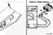
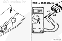
Depress the foot pedal (full-fuel) and measure the resistance again.
The multimeter
must show 200 to 1500 ohms. This resistance value
must be at least 1000 ohms lower than the resistance value of 1500 to 3000 ohms measured in the above check. If the resistance values are
not within the specification, there is a problem with wire 48 (accelerator position (+) 5-VDC supply) or wire 47 (accelerator position signal) in the OEM harness.
Repair the OEM harness according to the manufacturer’s procedures. If the resistance values in the two previous checks are within the specification, wire 48, 49, and 47
must still be checked for a short circuit to ground, a short circuit from pin to pin, and a short circuit to battery supply.
NOTE: When checking the OEM harness, inspect the bulkhead connector and other connectors in the circuit for corrosion or damage to the APS wire terminals.
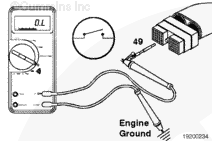
Insert a test lead into pin 48 (accelerator position (+) 5-VDC supply)
of the OEM harness connector and connect it to the multimeter positive probe. Touch the multimeter negative probe to the engine block ground and measure the resistance.
Remove the lead from pin 48 (accelerator position (+) 5-VDC supply)
and insert it into pin 49 (accelerator position return) of the OEM harness connector. Touch the multimeter negative probe to the engine block ground and measure the resistance.
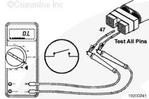
Remove the lead from pin 49 (accelerator position return)
and insert it into pin 47 (accelerator position signal). Touch the multimeter negative probe to the engine block ground and measure the resistance.
The multimeter
must show an open circuit (100k ohms or more).
If
any of these three resistance measurements are
not open, there is a short circuit to ground between the wires connected to pins 48, 49, or 47. Repair the OEM harness. Refer to the OEM troubleshooting and repair manual for the procedures.
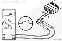
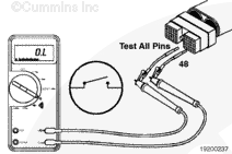
Insert the test lead into pin 48 (accelerator position (+) 5-VDC supply)
of the OEM harness connector. Insert the other lead into pin 6 of the connector. Connect the clips to the multimeter probes and measure the resistance.
Remove the lead from pin 6 and test all other pins in the connector, one at a time.
The multimeter
must show an open circuit (100k ohms or more) at all pins.
If the multimeter shows a closed circuit at any pin, there is a short circuit between wire 48 and any other wire that measured a closed circuit. Repair or replace the OEM harness. Refer to Procedure
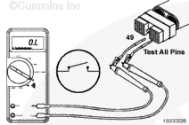
Remove the lead from pin 1 and test all other pins in the connector, one at a time.
The multimeter
must show an open circuit (100k ohms or more) in all pins.
If the multimeter shows a closed circuit at any pin, there is a short circuit between wire 47 and any other wire that measured a closed circuit. Repair the OEM harness according to the vehicle manufacturer’s procedures.
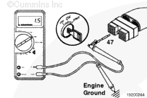
Turn the keyswitch to the ON position. Adjust the multimeter to measure VDC.
Insert a test lead into pin 48 (accelerator position (+) 5 VDC supply)
of the OEM harness connector. Connect the lead to the multimeter positive probe. Touch the multimeter negative probe to the engine block ground and measure the voltage.
Remove the lead from pin 48 and insert it into pin 49 (accelerator position return). Touch the multimeter negative probe to the engine block ground and measure the voltage.
Remove the lead from pin 49 and insert it into pin 47 (accelerator position signal). Touch the multimeter negative probe to the engine block and measure the voltage.
The voltage
must be 1.5 VDC or less.
If more than 1.5 VDC is measured at any pin, there is a short circuit from wire 48, 49, or 47 to a wire carrying power in the OEM harness.
NOTE: An external voltage source is any wire in the OEM harness that carries voltage.
Repair the OEM harness. Refer to Procedure
019-250. Connect all components after completing the repair.
Hello, I'm Jack, a diesel engine fan and a blogger. I write about how to fix and improve diesel engines, from cars to trucks to generators. I also review the newest models and innovations in the diesel market. If you are interested in learning more about diesel engines, check out my blog and leave your feedback.
View all posts by Jack
 CAUTION


;)
;)
;)
;)
;)
;)
;)
;)
;)
;)
;)
;)
;)
;)
;)
;)
;)
;)
;)
;)
;)
;)
;)
;)
;)
;)
;)
;)
;)
;)
;)
;)
;)
;)
;)
;)