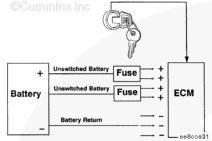
The ECM receives constant voltage from the batteries through the unswitched battery wires that are connected directly to the (+) positive battery post. There are two in-line 15-amp fuses in the unswitched battery wires to protect the ECM. The ECM receives switched battery input through the vehicle keyswitch wire when the vehicle keyswitch is turned on. The battery return wires are connected directly to the (-) negative battery post.
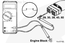
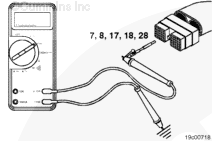
Insert a test lead into pin 29 of the OEM harness connector. Attach it to a multimeter probe. Touch the other multimeter probe to the engine block ground and measure the resistance. The multimeter
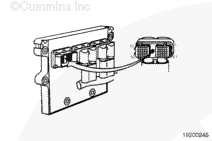
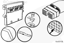
Check the battery return wires in the OEM harness for proper grounding. Disconnect the harness from the ECM. Check for damaged pins in the ECM and the harness.
Hello, I'm Jack, a diesel engine fan and a blogger. I write about how to fix and improve diesel engines, from cars to trucks to generators. I also review the newest models and innovations in the diesel market. If you are interested in learning more about diesel engines, check out my blog and leave your feedback.
View all posts by Jack


;)
;)
;)
;)
;)
;)
;)
;)
;)
;)
;)
;)