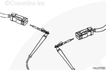
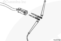
Touch one of the multimeter leads to the sensor supply wire, pin 1 (or A), of the temperature sensor harness connector on the ambient air temperature sensor end of the harness.
Touch the other multimeter lead to the sensor supply wire, pin 1 (or A), of the temperature sensor harness connector on the cab thermostat end of the harness.
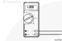
Repeat the check for the return wire. Measure the resistance from the return wire, pin 2 (or B), at the sensor end of the temperature sensor harness to the return wire, pin 3 (or C), at the thermostat end of the harness. Read the value displayed on the multimeter.
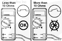
The multimeter must display a reading of less than 10 ohms, which is a closed circuit.
If the circuit is open, repair or replace the temperature sensor harness. Refer to 019-202 or Procedure 019-071 for harness replacement.
Connect all components after completing the repair.
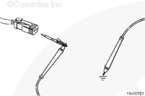
Touch one of the multimeter leads to the supply wire, pin 1 (or A), of the temperature sensor harness connector on the cab thermostat end of the harness.
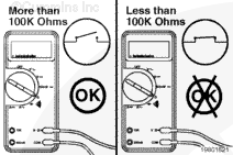
Touch one of the multimeter leads to the return wire, pin 2 (or B), of the temperature sensor harness connector on the cab thermostat end of the harness. Touch the other multimeter lead to ground. Read the value displayed on the multimeter.
The multimeter must display more than 100k ohms (open circuit). If the circuit is not open, there is a short circuit to ground.
Repair or replace the temperature sensor harness. Refer to Procedure 019-202 or Procedure 019-071.
Connect all components after completing the repair.
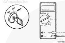
Touch one of the multimeter leads to the supply wire, pin 1 (or A), of the temperature sensor harness connector on the cab thermostat end of the harness.
Touch one of the multimeter leads to the return wire, pin 3 (or C), of temperature sensor harness connector on the cab thermostat end of the harness. Touch the other multimeter lead to ground.
Read the value displayed on the multimeter.
The multimeter must display less than 1.5 VDC. If the circuit is not less than 1.5 VDC, there is a short circuit to an external voltage source. Remove the external voltage source.
Connect all components after completing the repair.
Hello, I'm Jack, a diesel engine fan and a blogger. I write about how to fix and improve diesel engines, from cars to trucks to generators. I also review the newest models and innovations in the diesel market. If you are interested in learning more about diesel engines, check out my blog and leave your feedback.
View all posts by Jack
 CAUTION


;)
;)
;)
;)
;)
;)
;)
;)
;)
;)
;)
;)
;)
;)
;)
;)