Drain the air compressor tank and all lines before removing or installing the air compressor governor. Failure to drain the air compressor tank and lines of pressure could result in personal injury, mechanical damage, electrical damage, or all of the above.
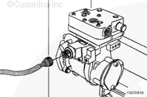
Lift up on the tab and disconnect the connector from the governor.
Drain the air compressor tank and all lines before removing or installing the air compressor governor. Failure to drain the air compressor tank and lines of pressure could result in personal injury, mechanical damage, electrical damage, or all of the above.
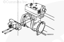
Make sure the new governor has an o-ring around the surface where it seals against the air compressor.
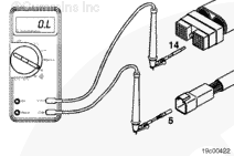
Do not use test leads other than Part Number 3822758. The connector will be damaged. The leads must fit tightly in the connector without expanding the pins of the connector.
Disconnect the actuator harness connector from the ECM. Disconnect the 6-pin electronic governor connector from the engine harness. Adjust the multimeter to measure resistance. Insert a test lead into pin 14 of the actuator harness connector, and connect it to the multimeter probe. Insert the other test lead into pin 5 of the 6-pin electronic governor connector, engine harness side, and connect it to the other multimeter probe. Measure the resistance.
The multimeter must show a closed circuit (10 ohms or less).
If the circuit is not closed, repair or replace the actuator harness. Refer to Procedures 019-204 019-206.
Check the return wire. Insert a test lead into pin 11 of the actuator harness connector. Insert the other test lead into pin 6 of the 6-pin electronic governor connector, engine harness side. Measure the resistance.
The multimeter must show a closed circuit (10 ohms or less).
If the circuit is not closed, repair or replace the actuator harness. Refer to Procedures 019-204 019-206.
Hello, I'm Jack, a diesel engine fan and a blogger. I write about how to fix and improve diesel engines, from cars to trucks to generators. I also review the newest models and innovations in the diesel market. If you are interested in learning more about diesel engines, check out my blog and leave your feedback.
View all posts by Jack
 WARNING


 CAUTION


;)
;)
;)
;)
;)
;)
;)
;)