Do not remove the pressure cap from a hot engine. Wait until the coolant temperature is below 50°C [120°F] before removing the pressure cap. Heated coolant spray or steam can cause personal injury.
WARNING
Coolant is toxic. Keep away from children and pets. If not reused, dispose of in accordance with local environmental regulations.
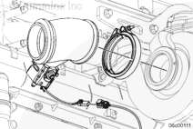
Drain the coolant.
For Signature™, ISX, and QSX15 engines, use the following procedure in the Signature™, ISX, and QSX15 Service Manual, Bulletin 3666239. Refer to Procedure 008-018 in Section 8.
When using solvents, acids, or alkaline materials for cleaning, follow the manufacturer’s recommendations for use. Wear goggles and protective clothing to reduce the possibility of personal injury.
WARNING
Wear appropriate eye and face protection when using compressed air. Flying debris and dirt can cause personal injury.
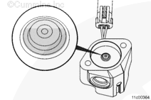
Inspect the injector tip.
Some carboning can occur on the tip of the injector.
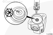
Spray the tip of the aftertreatment fuel injector with carburetor cleaner. When spraying, focus the spray on the tip of the injector. Use enough carburetor cleaner to fill the cavity surrounding the tip and to cover the tip.
Allow the carburetor cleaner to sit for 15 seconds so that it can break down and penetrate the debris that has collected in the tip area.
NOTE: Carburetor cleaner is the most effective solvent for this procedure. Do not substitute any other cleaning solvent.
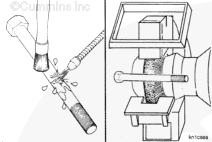
Use only a stiff brass brush with undamaged bristles to clean the tip of the aftertreatment fuel injector.
CAUTION
The use of a brush with damaged bristles will not be as effective.
CAUTION
The use of a steel wire brush or a steel wire wheel will cause permanent damage to the aftertreatment fuel injector.
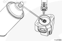
Use a brass brush to agitate the carburetor cleaner, focusing on the tip of the injector.
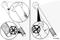
Repeat spraying and brushing for 1 minute. Often the carbon will be removed from the tip in a short period, but cleaning for a full minute will remove the carbon built up in the nozzle.
NOTE: The carbon this procedure is attempting to remove can often not be seen with the unaided eye. This carbon builds up in the nozzle tip area of the injector.
Clean the capscrews thoroughly with a wire brush, a soft wire wheel, or use a non-abrasive bead blast to remove deposits from the shaft and the threads.
Inspect the capscrews for damaged threads, corroded surfaces, or a reduced diameter (due to capscrew stretching).
Replace if necessary.
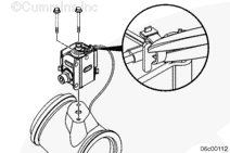
Inspect the harness and connector pins for the following:
Loose connector
Corroded pins
Bent or broken pins
Pushed back or expanded pins
Moisture in or on the connector
Missing or damaged connector seals
Dirt or debris in or on the connector pins
Connector shell broken
Wire insulation damage
Damaged connector locking tab.
Use the following procedure for general inspection techniques in the CM871 and CM876 Electronic Control Systems, ISX and ISM Engines Troubleshooting and Repair Manual, Bulletin 4021560. Refer to Procedure 019-361 in Section 19.
If damage resulted in coolant, oil, excessive fuel or excessive black smoke entering the exhaust system, the aftertreatment system must be inspected. Use the following procedure in the ISM, ISMe, and QSM11 Service Manual, Bulletin 3666322. Refer to Procedure 014-013 in Section 14.
Hello, I'm Jack, a diesel engine fan and a blogger. I write about how to fix and improve diesel engines, from cars to trucks to generators. I also review the newest models and innovations in the diesel market. If you are interested in learning more about diesel engines, check out my blog and leave your feedback.
View all posts by Jack
 WARNING


 CAUTION
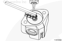


;)
;)
;)
;)
;)
;)
;)
;)
;)
;)
;)
;)
;)
;)
;)
;)
;)
;)
;)
;)