When using solvents or alkaline materials for cleaning, follow the manufacturer’s recommendations for use. Wear goggles and protective clothing to reduce the possibility of personal injury.
WARNING
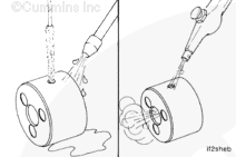
Wear appropriate eye and face protection when using compressed air. Flying dirt and debris can cause personal injury.
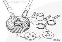
Clean the parts with solvent. Dry with compressed air.
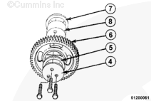
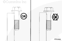
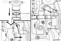
The shaft must pass through the gear and pilot into the rear thrust bearing. After installation, the shaft must protrude only slightly more than the thickness of the front thrust bearing. Excessive shaft protrusion beyond the thickness of the front thrust bearing indicates the shaft is not properly piloted into the rear thrust bearing.
Hello, I'm Jack, a diesel engine fan and a blogger. I write about how to fix and improve diesel engines, from cars to trucks to generators. I also review the newest models and innovations in the diesel market. If you are interested in learning more about diesel engines, check out my blog and leave your feedback.
View all posts by Jack


 WARNING


 CAUTION


;)
;)
;)
;)
;)
;)
;)
;)
;)
;)
;)
;)
;)
;)
;)
;)
;)
;)
;)
;)
;)
;)
;)
;)
;)
;)
;)
;)
;)
;)
;)
;)
;)
;)
;)
;)
;)
;)
;)
;)